


Airport Systems
SG-60 High Intensity Strobe System 2-3 Manual EPM-00000019 Rev A
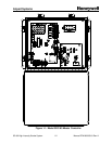
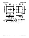
• SW2 – (Figure 2-10, Item 2, Page 2-25) This switch is used to set for
Catenary operation (suspended cable warning lights) and for Dual systems
(Red lights at night, and white strobes during the day).
§ SW2-1 – Set to ON (up) for Catenary system.
§ SW2-2 – Set to ON (up) for Dual system.
§ SW2-3 – Set to OFF (down). Reserved for future use.
• SW3 – (Figure 2-10, Item 8, Page 2-25) This switch is used to set the
termination resistor for the communications line.
§ SW3-1 – Set to ON if the Master Controller is at the end of the
communications line. In a typical installation, the communications lines
are terminated at the Master Controller and at the top level of
Flashheads. In this case, this switch should be set ON.
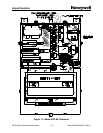
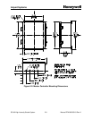
2.2.2 Flashhead Configuration
All of the configuration for the Flashhead in done on the digital controller board.
Because of the high voltage present in the Flashhead, there are interlock switches and
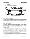
fuses as follows (Figure 1-2, Page 1-3):
• S1 POWER Interlock Switch: Three-position push/pull switch. When the
Flashhead door is opened, S1 interrupts AC line power to transformers T1 and
T2 when using 120VAC single-phase power. (When using 2-phase AC power,
S1 does not interrupt AC power to transformers T1 and T2.) When the
Flashhead door is opened, the PWR ON lamp DS1 to turn off. Also interrupts
power to relay K1, causing the high voltage to be shut off and the energy storage
capacitors to discharge. When door is open and S1 is pulled out manually, the
interlock is defeated, which allows the Flashhead to operate under power.
• S2 MODE Interlock Switch: Three-position push/pull switch. When the
Flashhead door is opened, transfers flash intensity mode select from remote
control (by SGC-60 Master Controller) to local control using switch S3. When
door is open and S2 is pulled out manually, the interlock is defeated, which
allows the Flashhead to operate under remote mode control.
• S3 MODE TEST Switch: Three-position rotary switch allows local flash intensity
mode selection (Day, Twilight or Night) for the individual Flashhead, while not
affecting the operation of any other Flashhead in the system.
• F1 Main Power Line Fuse: Provides protection for AC power to transformer T1.
Value varies with input AC line voltage. Refer to Section 7.0 for the correct fuse
values. Honeywell provides the correct fuse for the supplied power configuration.
• F2 Logic Power Line Fuse: Provides protection for the AC power to the logic
transformer T2. Value varies with input line voltage. Refer to Section 7.0 for the
correct fuse values. Honeywell provides the correct fuse for the supplied power
configuration.