


Airport Systems
SG-60 High Intensity Strobe System 2-6 Manual EPM-00000019 Rev A
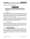
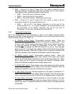
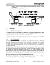
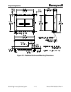
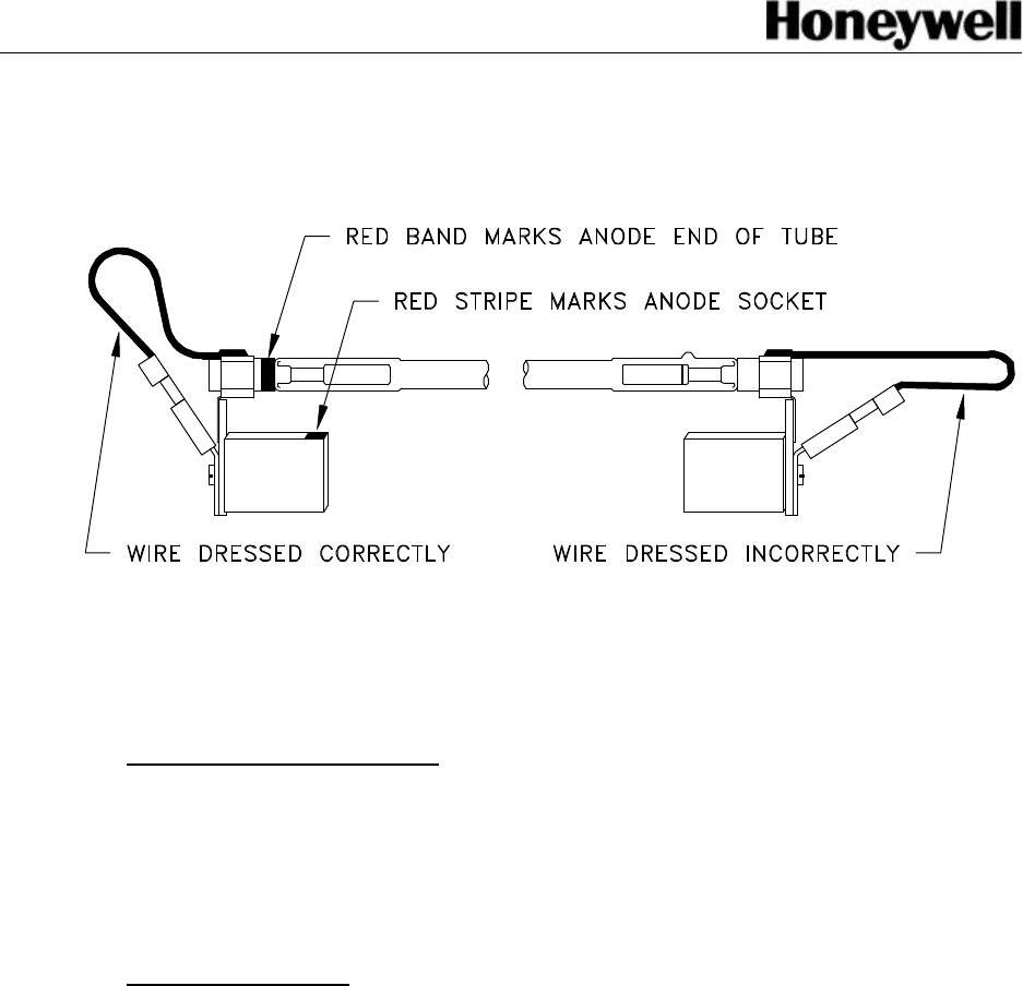
7. Refer to Figure 2-1 below. Dress the electrode wires away from the sides of
the reflector.
8. Close and fasten the Flashhead cover.
Figure 2-1: Flashtube Installation
2.3 Installation
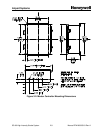
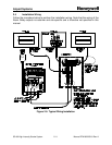
2.3.1 SGC-60 Master Controller
The Master Controller is connected to Flashheads via the data communications cable
provided by Honeywell. The length of this cable (up to 2500 feet) determines how far
the Master Controller can be mounted from the Flashheads.
A detailed drawing for mounting the Master Controller is shown in Figure 2-2, Page 2-9
2.3.2 SGF-60 Flashhead
Normally the Flashheads are mounted at the uppermost point and additional
referenced elevations on the structure. The Flashhead is connected to its Master
Controller via the data communications cable provided by Honeywell. The length of
this cable (up to 2500 feet) determines how far any Flashhead can be mounted from
the Master Controller.
Honeywell labels all the Flashheads with numbers ranging from 1 to 24 depending on
the number of required lights for the structure. Typically, the upper most level of lights
will contain the lights with numbers 1 through 3 or 4. If the structure has an
appurtenance of greater that 40 feet, an AOL (Antenna Obstruction Light) is required
and it will have a Flashhead Number of 1. The High Intensity Flashheads will start with
Flashhead Number 2. The flashheads should continue down the tower from the top
sequentially ending with the highest number at the bottom level.
The vent hole on the bottom surface of the power supply is covered with a solid plug
prior to shipping. Optional screened plugs are furnished separately.