


Airport Systems
SG-60 High Intensity Strobe System 3-10 Manual EPM-00000019 Rev A
during the daytime. In this case, the Master Controller will briefly try the Red Lights
each night until the top beacon is repaired.
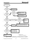
Troubleshooting Tip: To check system communications independent of most Flashhead
failures, place a jumper across TB6-1 and TB6-2, set SW2-2 On, and select Local
Night Mode from the switch panel. Because an Off Mode "flash" cannot fail, all the
Flashheads will reply OK if they can. Be sure to restore your Master Controller to its
proper configuration after testing.
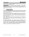
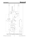
3.3.4 Communications Circuitry
The Master Controller transmits it flash requests, and receives replies via an RS485
serial link. The RS485 transceiver chip U2 is protected from voltage transients by
surge suppression devices and by transformer/optical isolation from chassis ground
and the rest of the digital board.
The microcontroller (U1) monitors its own transmissions. After each transmission, the
COM OK LED will be lit green if the transmission read back properly, or turned off it
there was a read-back failure. This only indicates that the transceiver chip on the
Master Controller is functioning properly -- it does not indicate that the Flashheads are
communicating properly.
SW3-1 (TERM) provides the necessary termination resistance for the RS485 serial
network. Each end of the cable should be terminated with a resistor. Typically the
Master Controller is installed at one end of the communications cable, in which case
SW3-1 should be ON.
The Master Controller board also provides the ground connection for the
communication cable shielding. The shield drain wire terminates at TB5-S (position 4),
and a heavy trace on the circuit board connects the shield to the lower right mounting
screw, and fast-on connector, both marked E1. The factory installs a grounding wire
from E1 to PB1-G. This should be the only place the communications shield is
grounded. You can check this by unplugging TB5, and measuring for an open circuit
between the (unplugged) TB5-S screw terminal and earth ground.