


Airport Systems
EPM-00000019-001 iv Rev A
3.3.4 Communications Circuitry..............................................................................................3-10
SECTION 4. TROUBLESHOOTING ............................................................................4-1
SECTION 5. MAINTENANCE ......................................................................................5-1
5.1 SGC-60 MASTER CONTROLLER ..................................................................................................5-1
Transformer Replacement............................................................................................................5-1
5.2 SGF-60 FLASHHEAD ..................................................................................................................5-2
5.2.1 Flashtube Replacement ...................................................................................................5-2
5.3 AMBIENT LIGHT SENSOR (PHOTOCELL).........................................................................................5-3
SECTION 6. REPLACEMENT PARTS ........................................................................6-1
SECTION 7. ANTENNA OBSTRUCTION LIGHT (AOL) .............................................7-1
TABLE OF FIGURES
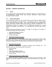
Figure 1-1: Model SGC-60 Master Controller...............................................................1-2
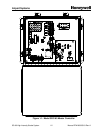
Figure 1-2: Model SGF-60 Flashhead..........................................................................1-3
Figure 2-1: Flashtube Installation.................................................................................2-6
Figure 2-2: Master Controller Mounting Dimensions....................................................2-9
Figure 2-3: Flashhead Outline and Mounting Dimensions............................................2-10
Figure 2-4: Typical Wiring Installation..........................................................................2-11
Figure 2-5: Flex Conduit Typical Installation Layout ..................................................2-15
Figure 2-6: Junction Box Wiring Details.....................................................................2-19
Figure 2-7: Flex Conduit Installation Detail ................................................................2-20
Figure 2-8: WC000001 Cable Overview ....................................................................2-21
Figure 2-9: Flashhead Cable.......................................................................................2-24
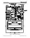
Figure 2-10: Master Controller Circuit Board .............................................................2-25
Figure 2-11: Flashhead Digital Control Board............................................................2-26
Figure 3-1: Master Controller Board Schematic .........................................................3-11
Figure 3-2: SGF-60 Flashhead System Schematic ....................................................3-12
Figure 3-3: SGF-60 Digital Board Schematic.............................................................3-13
Figure 3-4: SGF-60 Trigger/High-Voltage Board Schematic......................................3-14
Figure 4-1: General Troubleshooting – All Flashheads Stuck in Day Mode ................4-3
Figure 4-2: General Troubleshooting – Flashhead Does Not Flash.............................4-4
Figure 4-3: General Troubleshooting – Flashhead Stuck in Day Mode .......................4-5
Figure 4-4: Dual System-Specific Troubleshooting......................................................4-6
Figure 4-5: Catenary System-Specific Troubleshooting Chart.....................................4-7
Figure 5-1: SGC-60 Replacement Transformer ...........................................................5-1
Figure 5-2: Flashtube Installation.................................................................................5-3
Figure 7-1: SG-60 AOL Flashhead Mounting Dimensions ...........................................7-2
Figure 7-2: SG-60 AOL Power Supply Mounting Dimensions......................................7-3
Figure 7-3: SG-60 AOL Wiring Installation...................................................................7-4
Figure 7-4: SG-60 AOL Flashhead Component Locations...........................................7-5
Figure 7-5: SG-60 AOL Power Supply Component Locations......................................7-6
Figure 7-6: SG-60 AOL Schematic...............................................................................7-7