Airport Systems
SG-60 High Intensity Strobe System 2-30 Manual EPM-00000019 Rev A
7. Verify that the LED test sequence has started. The test sequence will
exercise every LED and relay (e.g. it will quickly sweep through the
Flashhead Status LEDs in red and green mode).
After the test sequence completes, the Flashhead status LEDs for the
selected number of Flashheads shall be lit red then change to green as
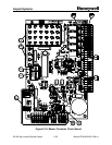
the Flashheads report (DS1 - DS24, Figure 2-10 Item 4, Page 2-25).
8. After 1 minute, verify the number of Flashhead status LEDs (DS1 - DS24,
Figure 2-10 Item 4, Page 2-25) that are lit green matches the total number
of white Flashhead lights (including AOL) on the tower (if there are n
Flashheads on the tower, Flashhead status LEDs DS1 - DSn shall be lit
green). Verify that the remaining unused Flashhead status LEDs (DSn+1
- DS24) are turned off.
Once all the flashheads report good (green), the relay monitor LEDs
should display as follows: DS29-DS32 GREEN, DS33 OFF (DS29 -
DS33, Figure 2-10 Item 5, Page 2-25).
9. Verify Photocell status LED DS28 (Figure 2-10, Item 3, Page 2-25) is lit
green.
10. Verify Day Mode LED DS25 (Figure 2-10, Item 3, Page 2-25) is lit red,
and the Twilight and Night LEDs (DS26 and DS27 respectively (Figure
2-10, Item 3, Page 2-25)) are not lit.
11. Hold down the RESET switch for approximately 1 second and verify the
LED test sequence has restarted.
12. Wait 1 minute and measure the voltage between TB1-1 and TB1-2 to
verify the voltage is 12-18 VAC. Repeat steps 7 - 10 to assure proper
recovery after reset.
2.6.4 Verify Local Mode Operation
All switches and indicators listed in this section are in the Master Controller.
2.6.4.1 Day Mode:
1. Verify MODE Switch is set to DAY.
2. Verify Day mode LED DS25 (Figure 2-10 Item 3, Page 2-25) is lit red.
3. After about 6 seconds, verify all Flashheads are flashing in sync and in
Day mode (maximum brightness).
4. Verify that the Flashhead Status LED for each Flashhead on the tower is
lit green (including any AOL). Unused Flashhead status LEDs shall be
off. (DS1 - DS24: Figure 2-10, Item 4, Page 2-25)
5. Verify relay status LEDs DS29-DS32 are lit green, ans DS33 is OFF.
(Figure 2-10, Item 5, Page 2-25)


