


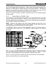
Airport Systems
SG-60 High Intensity Strobe System 2-21 Manual EPM-00000019 Rev A
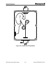
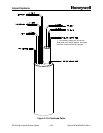
The flex conduit will need to be properly mounted to the horizontal and vertical struts by
way of the supplied 20-inch cable ties. These cable ties should be placed at a
minimum of 3 feet apart for proper bonding to the tower structure. The distance
between the cable ties may need to be reduced if the installer sees that the 3-foot
distance will not allow for proper bonding and securing to the tower.
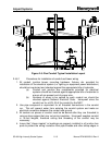
Figure 2-5, Page 2-15 depicts a standard installation layout for the Flashhead pigtails
and flex conduit.
2.4.7.2 Splicing Details for WC000001 Cable
The installation of the data/communication cable is the most important part of the High
Intensity Lighting system installation. Without a sound connection for the data cable,
the entire system will not work properly. Insure that the following steps are followed to
insure a proper installation and connection.
NOTE: Splicing of the cables at any other location besides the light level is not
recommended. The intermediate junction boxes between the light levels should be
used as pull boxes and for strain relief only, with no splices.
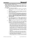
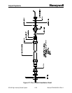
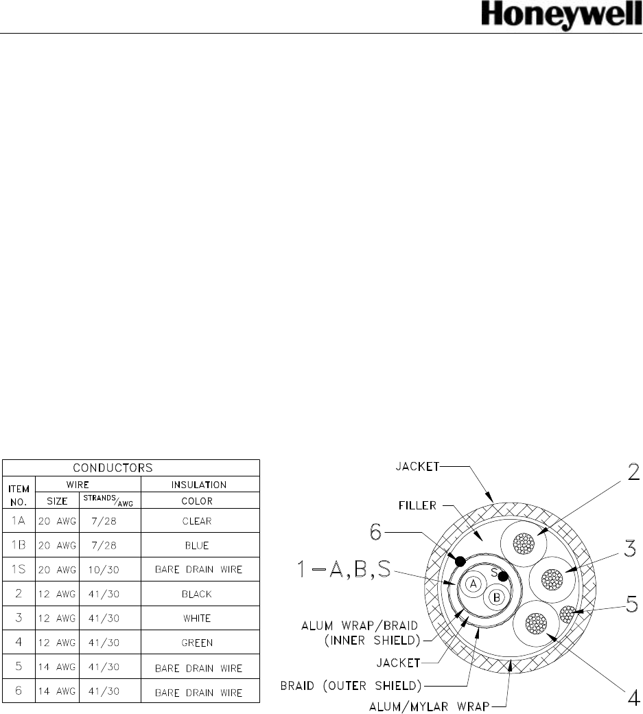
The WC000001 cable is a multi-conductor cable that is used for the interconnection of
the flashhead to the junction box. The WC000001 cable consists of the following
wires/cable:
Figure 2-9: WC000001 Cable Overview
Item 1 (A, B, S) is the data/communication cable that is used to transmit all the data
from the master controller, SGC-60, to the flashhead, SGF-60. Without a proper
connection, the lighting system will flash erratically, or default to Day mode.
Items 2, 3, and 4 are used for the power input from the junction box to the flashhead.
Item 5 is the Drain Wire for the outer cable shield.