


Airport Systems
SG-60 High Intensity Strobe System 2-13 Manual EPM-00000019 Rev A
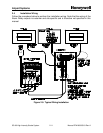
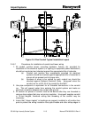
2.4.4 Master Controller Wiring For Dual Systems
If your installation is a Dual (Red/White) system, you must make additional connections
to coordinate between the High Intensity Strobe System and the Red Light System.
See the sections below for wiring details. For configuration switch settings for a Dual
system, see 2.2.1.3 on Page 2-2.
2.4.4.1 Controlling the Red Light System
The Master Controller uses Relay K4 to control the Red Light System. The Relay K4
contacts should be wired to the Red Light System in such a way that when K4 is
energized, the Red Lights turn off, and when K4 is de-energized, the Red Lights turn
on.
Typically this is done by disconnecting the Red Light System photocell, and wiring
those photocell inputs to the Relay K4 contact. The contacts are rated for up to 5A,
and up to either 30VDC or 250VAC.
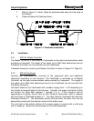
If your red light system has a Honeywell 9LCA-Series Red Light Controller, the 9LCA
photocell is not used. Instead of connecting the 9LCA photocell to 9LCA terminal TB3,
make the following connections:
Master Controller TB3-C4--------------- to -------- 9LCA Red Light Controller TB3-B
Master Controller TB5-NO4 ------------ to ----------9LCA Red Light ControllerTB3-R
Configure the 9LCA Red Light Controller to use Automatic mode control. Other Red
Light Systems may require different connections. Refer to the Tower Kit drawing (if
Honeywell provided both systems as a kit), refer to the Red Light System's manual, or
contact Honeywell for assistance.
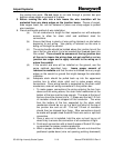
2.4.4.2 Responding to Top Red Beacon Failures
When a top-level red beacon fails at night, a Dual system must switch from red to white
lights. The Master Controller will switch to the white strobes at night if it detects an
open circuit between TB6-1 and TB6-2 ("EXT RED").
Install external wiring must in a single electrical loop from TB6-1 to TB6-2 in such a way
that the loop is closed when all the top-level red beacons are operating correctly, and
the loop is opened (broken) when any top-level red beacon fails.
The External Red Ready indicator (LED DS36 -- Item 10 in Figure 2-10, Page 1-2)
turns on to indicate a closed loop (Red Lights OK), and turn off to indicate an open loop
(Red Light Failure).