


Airport Systems
SG-60 High Intensity Strobe System 2-4 Manual EPM-00000019 Rev A
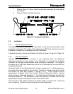
2.2.2.1 Power Configuration
The Flashhead(s) are factory set for the correct AC input line voltage. However, the
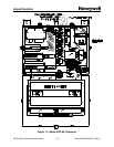
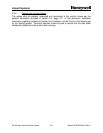
user shall verify that the AC line voltage selector block (located on the transformer
board on top of transformer T1, Figure 1-2, Page 1-3) is labeled with the correct AC
line voltage used at the site. For example, voltage selector block part number 77-3319
is labeled for 120VAC. If the voltage selector block is not labeled for the correct AC
line voltage used at the site, the correct voltage selector block must be obtained from
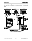
Honeywell, and the AC input wiring to transformer T2 must also be verified and
corrected if necessary according to Figure 3-2, Page 3-12.
2.2.2.2 Configuration Switches
• SW1 – (Figure 2-11, Item 2, Page 2-26) This switch is used to reset the
processor
§ Press and hold – resets the processor and tests the automatic power
reset circuit. Press and hold SW1 until the 5v power indicator (DS1,
Figure 2-11, Item 1, Page 2-26) turns OFF momentarily then release.
• SW2 – (Figure 2-11, Item 4, Page 2-26) This switch is used to set special
operation options. Set all four switches to OFF unless your system meets
one of the two conditions below:
CONDITION 1: You have a Catenary System
§ SW2-1 – Set ON for all Flashheads on top level of a Catenary installation.
§ SW2-2 – Set ON for all Flashheads on bottom level of Catenary
installation.
§ SW2 -1 & -2 – Set both to ON for all Flashheads on middle level of a
Catenary installation.
CONDITION 2: You have Dual (Red/White) system with an older-model
Master Controller.
§ SW2-3 – Set to ON. This is provided for backward compatibility with
older installations only. For new installations this switch is always
OFF. For older white-only installations this switch is also OFF.
To determine if an existing installation has an older Master Controller,
refer to the new Master Controller in Figure 2-10, Page 2-25. Older
Master Controllers do not have terminals TB5-TB9, or an EXT RED switch
SW2-2 (Item 2 in the figure).
Note: Switch SW2-4 is a spare reserved for future use.