


Airport Systems
SG-60 High Intensity Strobe System 3-6 Manual EPM-00000019 Rev A
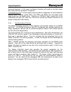
3.2.2.4 Flash Control
To fire the flashtube, the Digital Board pulls down the trigger request line (P2-17) for
about 500uS. This signals the Trigger/High-Voltage Card to trigger the flashtube.
The Digital Board will issue its trigger request on a T2 zero-crossing. (Normally, the
first zero-crossing it detects after receiving a flash request from the Master Controller.)
In Day and Twilight modes, the Digital Board will issue a single trigger request. In
Night mode, the Digital Board will issue a series of 15 pulses at consecutive zero
crossings.
The zero crossing is determined from a 12VAC output from Flashhead transformer T2.
(T2-15 and T2-16, entering the Digital Board at P2-21 and P2-23 respectively). As a
failsafe measure, the Digital Board will issue a trigger request after a timeout period
even if no zero crossing is detected.
When acting as a Top or Bottom Catenary Flashhead, the Digital Board will delay by
1/13 and 3/13 seconds respectively before looking for the first T2 zero-crossing, to
achieve the required Catenary flash sequence:
(Middle -- 1/13 s, Top -- 2/13 s, Bottom -- 10/13 s, Middle -- etc.)
The SW2-1 and SW2-2 switches instruct the Digital Board to apply the correct timing
delays for Catenary Systems. The faster flash rate (60 flashes per minute) is set by an
option on the Master Controller (SW2-1).
3.2.2.5 Flash Feedback
The Digital Board monitors the current discharged through the flashtube with the
Flashhead current sense transformer T3. The T3 output is used to peak-charge a
capacitor C17. The microcontroller reads the captured voltage level at the capacitor
with A/D converter (U5) before and after the flash to determine if the flash occurred
successfully. C17 will fully discharge before the next flash.
The yellow LED DS2 indicates the results of the most recent flash. If the Digital Board
considered the flash successful the DS2 will be on. If the Digital Board considers the
flash to have failed, DS2 will be off.
If four consecutive flashes fail, the Digital Board reports a Flash/Fail alarm to the
Master Controller (per FAA specifications).
The T3 transformer connections are polarity sensitive. If the wires are reversed, the
Digital Board will not be able to detect good flashes, especially in Day and Twilight
modes.
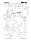
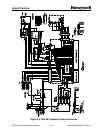
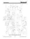
3.2.3 SGF-60 Trigger/High-Voltage Board
The Trigger/High-Voltage combines two completely independent functions: high
voltage rectification and flashtube triggering.