


Airport Systems
SG-60 High Intensity Strobe System 2-12 Manual EPM-00000019 Rev A
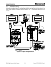
2.4.1 Master Controller to Photocell Wiring
The photocell is supplied with a length of wire attached. If a longer wire is needed, this
should be accomplished using a junction box. Make the interconnect between the
external Photocell and the Master Controller TB2 per Figure 2-5, Page 2-11, as
follows.
Black wire Photocell ------------------------ to -----------Master Controller TB2-B
White wire Photocell ------------------------ to ---------- Master Controller TB2-W
Red wire Photocell ------------------------ to -----------Master Controller TB2-R
2.4.2 Master Controller Data/Communications Wiring
Typically, the data/communications wiring is done with Honeywell P/N WC000002, a
shielded, twisted-pair cable. It has one pair of conductors, and a drain wire for making
shield connections. This cable is routed up the structure in the same conduit as the
Flashhead power wiring. Connect the data cable wires to Master Controller TB5
according to Figure 2-5, Page 2-11, and as follows:
White or Clear wire (Data signal "A") ------- to ----------------Master Controller TB5-A
Blue wire (Data signal "B")--------------------- to ----------------Master Controller TB5-B
Shield drain wire (Data shield) ----------- to --------------Master Controller TB5-S
(TB5-S is position 4)
The Data Shield (TB5-S) is grounded by the factory-installed wire that connects
the E1 ground lug on the Master Controller circuit board to PB1-G.
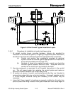
If you need to connect a Flashhead directly to the Master Controller using the data
cable integrated into Flashhead Cable WC000002, use the following connections.
White or Clear wire-----Master Controller TB5-A -----------to---- Flashhead TB1-4
Blue wire-------------------Master Controller TB5-B -----------to ---- Flashhead TB1-5
Inner Shield ---------------Master Controller TB5-S (4) -------to ---- Flashhead TB1-6
Outer Shield ---------------------------------------------------------not connected at either end
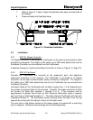
2.4.3 Master Controller Power Wiring
Make the connections for incoming AC line power to Master Controller PB1 per Figure
2-5, Page 2-11 as follows. These wires (or cable) are not supplied by Honeywell. A
separate circuit breaker is recommended for the Master Controller. The Master
Controller may, if desired, use a different AC line voltage than the Flashheads.
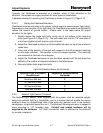
The wire colors below are typical for single-phase power. Be sure to check your own
installation colors.
Black wire (Phase or hi) ----------------------------- to ----------- Master Controller PB1-L
White wire (Phase or neutral) ---------------------- to -------- Master Controller PB1-L/N
Green wire (Equipment ground) ----------------to--------- Master Controller PB1-G