


Airport Systems
SG-60 High Intensity Strobe System 2-14 Manual EPM-00000019 Rev A
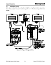
If your red light system has a Honeywell 9LCA Series Red Light Controller, locate the
Alarm terminals and Flasher Bypass terminals corresponding to the top beacon, and
make the following connections:
Master Controller TB6-1-----------------to ----------------------9LCA Flasher Bypass C1
9LCA Flasher Bypass NC1 -------------to----------------------------9LCA Alarm Card C1
Master Controller TB6-2-----------------to --------------------------9LCA Alarm Card NC1
Note: Usually the top beacon terminals are found on the top/left Flasher Bypass Card
(TB4), and the left channel of the top Alarm Card (TB3).
Other Red Light Systems may require different connections. Refer the to Tower Kit
drawing (if both systems were provided as a kit by Honeywell), the Red Light System's
manual, or contact Honeywell for assistance.
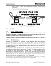
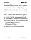
2.4.5 Flashhead Wiring
Incoming AC power and data communications enter the Flashhead in a single cable,
Honeywell P/N WC000001, that combines three wires for AC power with a
twisted-pair/double-shielded data cable (See Figure 2-9, Page 2-21). Typically,
Flashheads are supplied with a 10-20 foot length of this cable already installed.
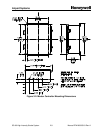
Should you need to install or replace this cable, make the connections for incoming AC
power and data to Flashhead TB1 per Figure 2-5, Page 2-11, and Figure 2-10, Page 2-
24, as follows.
Green wire (Equipment ground) ------------------------to----------------- Flashhead TB1-1
White wire (Phase or neutral) ---------------------------to----------------- Flashhead TB1-2
Black wire (Phase or hi) ----------------------------------to----------------- Flashhead TB1-3
Data Cable
White or Clear wire (Data signal "A") ------------to----------------- Flashhead TB1-4
Blue wire (Data signal "B") --------------------------to----------------- Flashhead TB1-5
Inner shield (Data shield)----------------------------to----------------- Flashhead TB1-6
Outer shield-------------------------------------------------------- trim short; not connected
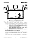
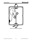
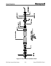
2.4.6 Conduit and Tower Wiring Detail
This section details a standard practice of installing conduit and the related tower
lighting wires for the system. Please use this guide to help install the wires into the
conduit system. The wires and cables for the SG-60 High Intensity system need to be
run properly to insure that the system will work properly. Wire insulation that is
damaged will lead to a system that will not function properly and may void the warranty.
Insure that the following procedure is followed. Pay close attention to all bold text.