


4
PARAMETERS
93
Control mode
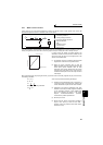
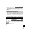
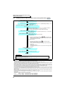
(3) Vector control test operation (Pr. 800 = "9")
⋅ Speed control test operation can be performed even when the motor is not connected.
The speed calculation value changes to track the speed command and the transition can be checked with the
operation panel and analog signal output at FM and AM.
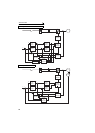
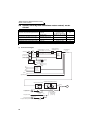
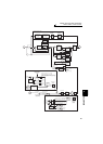
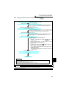
(4) Control method switching by external terminals (RT signal, X18 signal)
⋅ The switching of the control method (V/F control, Advanced magnetic flux vector control, Real sensorless vector
control and vector control) by the external terminal may be made in either of the following two ways: switching by
the second function selection signal (RT), or V/F switching signal (X18).
⋅ Two types of control method can be switched with the RT signal by setting the type of motor to be used as second
motor in Pr. 450 Second applied motor and control method of the motor in Pr. 451 Second motor control method selection.
Turn ON the RT signal to select the second function.
⋅ For switching by the X18 signal, setting "12, 14, 16, 18, 20" in Pr. 81 Number of motor poles and turning the X18
signal ON switches the present selected control method (Advanced magnetic flux vector control, Real sensorless
vector control and vector control) to V/F control. In this case, use this signal only for changing the control method of
one motor since second function as electronic thermal relay characteristic, etc. cannot be changed. (Use the RT
signal to change the second function.)
For the terminal used for X18 signal input, set "18" in any of Pr. 178 to Pr. 189 (input terminal function selection) to
assign the function.
*1 V/F control is selected when "12, 14, 16, 18, 20" is set in Pr. 81 and the X18 signal is ON. When the X18 signal is not assigned, turning the RT
signal ON selects V/F control as the RT signal shares this function.
CAUTION
⋅ Since current is not detected and voltage is not output, monitors related to current and voltage such as output current and output
voltage, etc. and output signals do not function.
⋅ For speed calculation, speed is calculated in consideration of Pr. 880 Load inertia ratio.
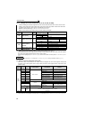
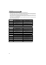
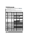
First Motor Control Method
Second Motor Control Method
(RT signal is on)
Pr. 450
Setting
Pr. 453, Pr. 454
Setting
Pr. 451
Setting
V/F control
V/F control
9999 ⎯⎯
Other than
9999
9999 ⎯
Advanced magnetic flux vector control
Other than
9999
20, 9999
Real sensorless vector control 10 to 12
Advanced magnetic flux vector
control
Real sensorless vector control
Same control as the first motor
*1 9999 ⎯⎯
V/F control
Other than
9999
9999 ⎯
Advanced magnetic flux vector control
Other than
9999
20, 9999
Real sensorless vector control 10 to 12
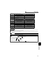
REMARKS
⋅ The RT signal is assigned to the terminal RT in the initial setting. By setting "3" in any of Pr. 178 to Pr. 189 (input terminal function
selection), you can assign the RT signal to the other terminal.
⋅ The RT signal acts as the second function selection signal and makes the other second functions valid. (Refer to page 235.)
⋅ The control method could be changed by external terminals (RT signal, X18 signal) while the inverter is stopped.
If a signal is switched during the operation, the control method changes after the inverter stops.