


57
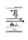
EMC and leakage currents
3
PRECAUTIONS FOR USE OF THE INVERTER
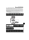
3.1.4 Harmonic Suppression Guidelines
Harmonic currents flow from the inverter to a power receiving point via a power transformer. The Harmonic
Suppression Guidelines were established to protect other consumers from these outgoing harmonic currents.
The three-phase 200V input specifications 3.7kW or less are previously covered by "Harmonic Suppression Guidelines
for Household Appliances and General-purpose Products" and other models are covered by "Harmonic Suppression
Guidelines for Consumers Who Receive High Voltage or Special High Voltage". However, the general-purpose inverter
has been excluded from the target products covered by "Harmonic Suppression Guidelines for Household Appliances
and General-purpose Products" in January 2004. Later, this guideline was repealed on 6 September 2004. All
capacities of all models are now target products of "Harmonic Suppression Guidelines for Consumers Who Receive
High Voltage or Special High Voltage" (hereinafter referred to as "Specific Consumer Guidelines").
"Specific Consumer Guidelines"
This guideline sets forth the maximum values of harmonic currents outgoing from a high-voltage or especially high-
voltage consumer who will install, add or renew harmonic generating equipment. If any of the maximum values is
exceeded, this guideline requires that consumer to take certain suppression measures.
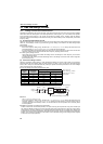
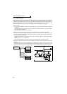
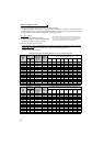
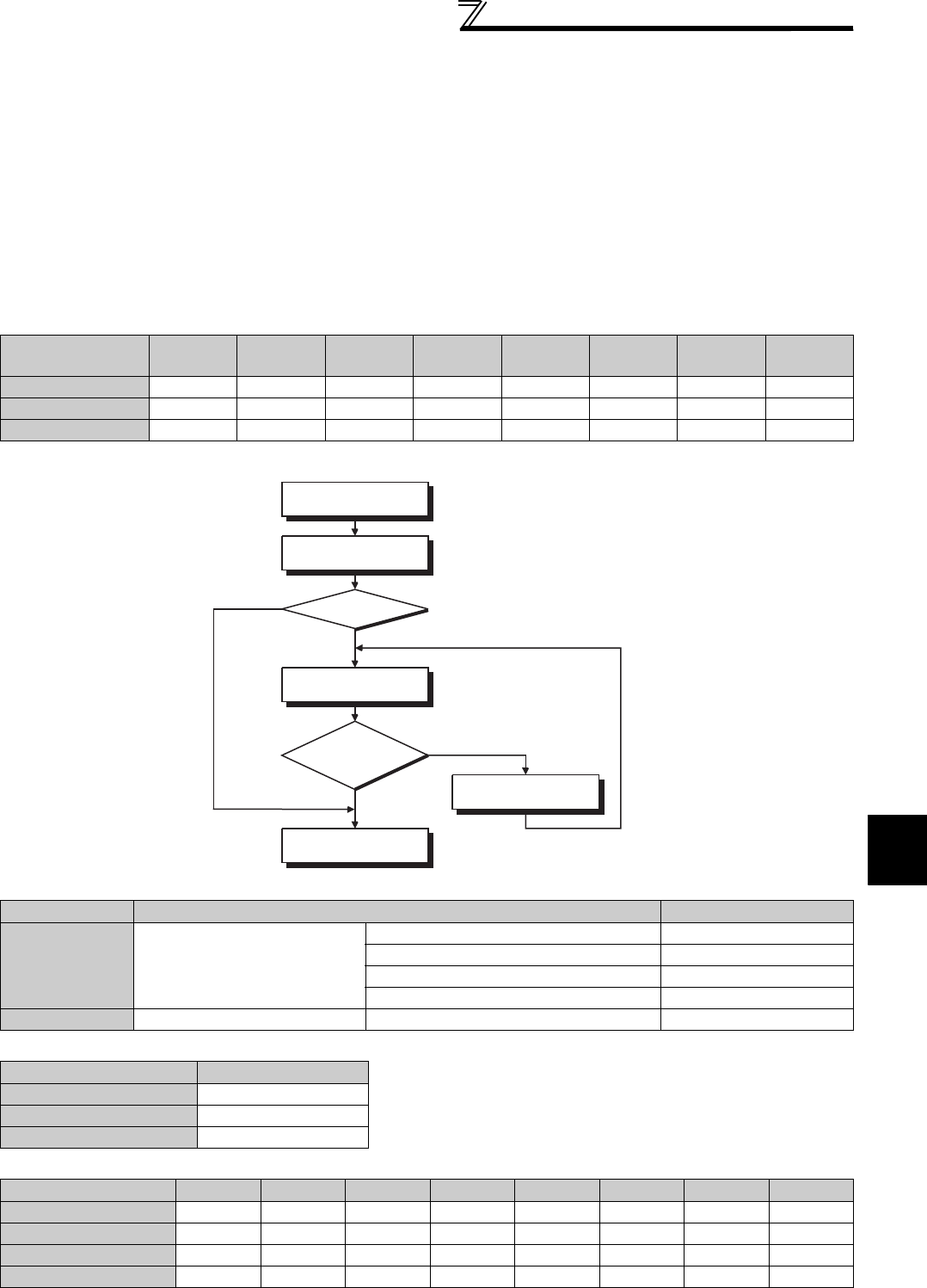
(1) Application of the Specific Consumer Guidelines
Table 1 Maximum Values of Outgoing Harmonic Currents per 1kW Contract Power
Received Power
Voltage
5th 7th 11th 13th 17th 19th 23rd Over 23rd
6.6kV 3.5 2.5 1.6 1.3 1.0 0.9 0.76 0.70
22kV 1.8 1.3 0.82 0.69 0.53 0.47 0.39 0.36
33kV 1.2 0.86 0.55 0.46 0.35 0.32 0.26 0.24
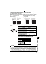
Table 2 Conversion factors for FR-A700 series
Class Circuit Type Conversion Factor (Ki)
3
Three-phase bridge
(Capacitor smoothing)
Without reactor K31 = 3.4
With reactor (AC side) K32 = 1.8
With reactor (DC side) K33 = 1.8
With reactor (AC, DC sides) K34 = 1.4
5 Self-excitation three-phase bridge When high power factor converter is used K5 = 0
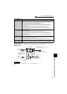
Table 3 Equivalent Capacity Limits
Received Power Voltage Reference Capacity
6.6kV 50kVA
22/33kV 300kVA
66kV or more 2000kVA
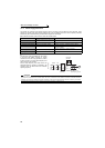
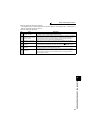
Table 4 Harmonic content (Values of the fundamental current is 100%)
Reactor 5th 7th 11th 13th 17th 19th 23rd 25th
Not used 65 41 8.5 7.7 4.3 3.1 2.6 1.8
Used (AC side) 38 14.5 7.4 3.4 3.2 1.9 1.7 1.3
Used (DC side) 30 13 8.4 5.0 4.7 3.2 3.0 2.2
Used (AC, DC sides) 28 9.1 7.2 4.1 3.2 2.4 1.6 1.4
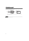
Install, add or renew
equipment
Calculation of equivalent
capacity total
Equivalent
capacity total
Calculation of outgoing
harmonic current
Not more than
harmonic current upper
limit?
Harmonic suppression
measures unnecessary
Harmonic suppression
measures necessary
Equal to or less
than upper limit
More than upper limit
Above reference
capacity
Equal to or less
than reference
capacity