


4
PARAMETERS
133
Position control by vector control
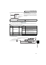
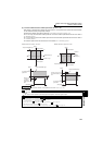
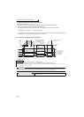
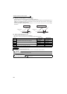
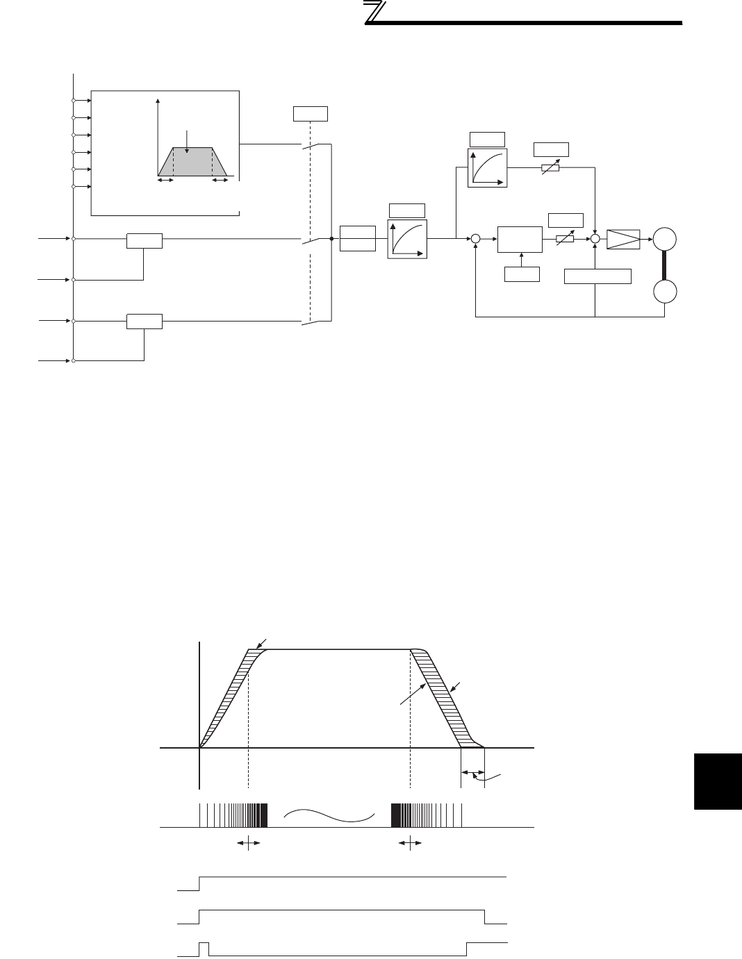
(2) Control block diagram
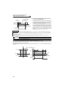
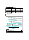
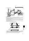
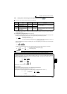
(3) Example of operation
The speed command given to rotate the motor is calculated to zero the difference between the number of internal
command pulse train pulses (when Pr. 419 = 0, the number of pulses set by parameter (Pr. 465 to Pr. 494) is changed to
the command pulses in the inverter) and the number of pulses fed back from the motor end encoder.
1)When a pulse train is input, pulses are accumulated in the deviation counter and these droop pulses act as position
control pulses to give the speed command.
2)As soon as the motor starts running under the speed command of the inverter, the encoder generates feed back
pulses and the droop of the deviation counter is counted down. The deviation counter maintains a given droop pulse
value to keep the motor running.
3)When the command pulse input stops, the droop pulses of the deviation counter decrease, reducing the speed. The
motor stops when there are no droop pulses.
4)When the number of droop pulses has fallen below the value set in Pr. 426 In-position width , it is regarded as
completion of positioning and the in-position signal (Y36) turns ON.
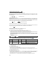
⋅ For simple position control function by contact input, the STF and STR terminals provide the forward (reverse)
command signal. The motor can run only in the direction where the forward (reverse) signal is ON. Turning the STF
signal OFF does not run the motor forward and turning the STR signal OFF does not run the motor reverse.
⋅ The pulse train is rough during acceleration and coarse at the maximum speed. During deceleration the pulse train is
rough and at last there are no pulses. The motor stops shortly after the command pulses stop.
This time lag is necessary for maintaining the stop accuracy and called stop settling time.
RH
RM
RL
REX
STF
STR
Pr. 4 to 6
Pr. 24 to 27
Pr. 232 to 239
Pr.7
Pr. 465 to Pr. 494
travel
Multi-speed,
communication
0
Pr. 419
Position command
source selection
1
Pr. 420
Pr. 421
Position command
acceleration/deceleration
time constant
Pr. 424
Position feed
forward
command filter
Pr. 425
Command pulse selection
Electronic
gear
Position feed
forward gain
Pr. 423
+
-
Deviation
counter
Position
loop gain
Pr. 422
+
+
Encoder
IM
Speed control
-
Clear signal
selection
Pr. 429
Differentiation
(Pr. 44, Pr. 110)(Pr. 45, Pr. 111)
Pr.8
Command pulse selection
Command pulse
Command pulse
Pulse train
sign
PGP, PP
PGN, NP
JOG
NP
(FR-A7AL)
Command pulse
(FR-A7AL)
2
Pr. 428
Pr. 428
Acceleration
Time
Deceleration
Stop settling time
Motor speed
Pulse distribution
Droop pulse value
Pulse train Rough Fine Rough
LX signal
Servo on
STF (STR)
Forward (reverse)
Y36 signal
In-position signal
Command pulse frequency
[PPS]
Motor speed [r/min]