


163
V/F pattern
4
PARAMETERS
4.10.3 Elevator mode (automatic acceleration/deceleration) (Pr. 61, Pr. 64, Pr. 292)
(1) Elevator mode
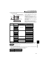
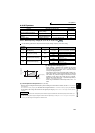
⋅ When "5" or "6" is set in Pr. 292 Automatic acceleration/deceleration , elevator mode is selected and each setting is
changed as in the table below.
⋅ Enough torque is generated during power driving and the torque boost value is automatically changed during
regeneration and operation without load so that overcurrent protection function does not activate due to over
excitation.
⋅ When operating the elevator with load more than the rated inverter current, the maximum torque may become
insufficient. For the elevator without counterweight, setting "2 or 3" (for elevator load) in Pr. 14 Load pattern selection
and an appropriate value in Pr. 19 Base frequency voltage will generate larger maximum torque than when elevator
mode is selected.
(2) Adjustment of elevator mode (Pr. 61, Pr. 64)
⋅ By setting the adjustment parameters Pr. 61 and Pr. 64, the application range can be made wider.
Operation matching a load characteristic of elevator with counterweight can be performed.
Parameter
Number
Name
Initial
Value
Setting Range Description
61 Reference current 9999
55K or lower 0 to 500A
Set the reference current for elevator mode.
75K or higher 0 to 3600A
9999 Rated inverter current value reference
64
Starting frequency for
elevator mode
9999
0 to 10%
Set the starting frequency for the elevator mode.
9999 Starting frequency 2Hz
292
Automatic acceleration/
deceleration
0
0 Normal operation mode
1
Minimum acceleration/
deceleration mode (without brake)
(Refer to
page 180.)
11
Minimum acceleration/deceleration
mode (with brake)
3
Optimum acceleration/
deceleration mode
5
Elevator mode 1
(stall prevention operation level 150%)
6
Elevator mode 2
(stall prevention operation level 180%)
7, 8
Brake sequence mode 1, 2
(Refer to page 217.)
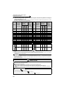
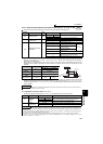
Name Normal Mode
Elevator Mode
Pr. 292 = 5 Pr. 292 = 6
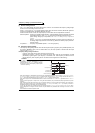
Torque boost
Pr. 0
(6/4/3/2/1%)
Changes according to the output
current (right chart)
Starting
frequency
Pr. 13 (0.5Hz)
Pr. 64 (2Hz)
Accelerate after maintaining 100ms
Base frequency
voltage
Pr. 19 (9999) 220V (440V)
Stall prevention
operation level
Pr. 22 (150%) etc. 150% 180%
REMARKS
⋅ Stall prevention operation level automatically decreases according to the electronic thermal relay function cumulative value, to
prevent inverter overload trip (E.THT, E.THM).
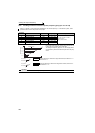
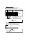
Parameter
Number
Name Setting Range Description
61
Reference
current
55K or lower 0 to 500A For example, when the motor and inverter are different in
capacity, set the rated motor current value. Set reference
current (A) of the stall prevention operation level
75K or higher 0 to 3600A
9999 (initial value) The rated inverter output current is defined as reference.
64
Starting
frequency for
elevator mode
0 to 10Hz Set the starting frequency for the elevator mode.
9999 (initial value) Starting frequency 2Hz
REMARKS
⋅ Even if elevator mode has been selected, inputting the jog signal (jog operation), RT signal (second function selection) or X9
signal (third function selection) during an inverter stop will switch to the normal operation and give priority to jog operation or
second and third function selection. Note that JOG and RT signal input is invalid even if JOG signal and RT signal are input
during operation with acceleration/deceleration selected.
⋅ Elevator mode is invalid when Advanced magnetic flux vector, Real sensorless vector control or vector control is selected.
⋅ Since the Pr. 61 and Pr. 64 settings automatically return to the initial value (9999) if the Pr. 292 setting is changed, set Pr. 292 first
when you need to set Pr. 61 and Pr. 64.
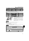
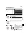
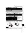
V/F
V/F
V/F
6%
Pr.292= "5"
Driving
current
(%)
When Pr.0=6%
Torque boost (%)
Regenerative
current
0
Pr.0
3%
100
115
Pr.292= "6"
120 140
Torque boost 0%