


454
Outline dimension drawings
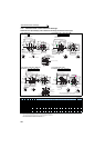
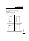
7.4.2 Dedicated motor outline dimension drawings
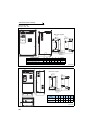
Dedicated motor (SF-V5RU(H)) outline dimension drawings (standard horizontal type)
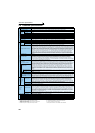
Dimensions table (Unit: mm)
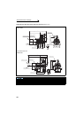
Note)1. Install the motor on the floor and use it with the shaft horizontal.
2.
Leave an enough clearance between the fan suction port and wall to ensure adequate cooling.
Also, check that the ventilation direction of a fan is from the opposite load side to the load side.
3 The size difference of top and bottom of the shaft center height is
4 The 400V class motor has -H at the end of its type name.
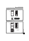
Frame Number 90L
SF-V5RU(H)
Frame Number 100L, 112M, 132S, 132M
SF-V5RU(H) , , ,
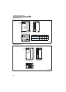
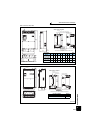
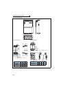
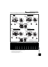
Frame Number 160M, 160L, 180M, 180L
SF-V5RU(H) , , ,
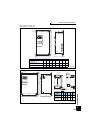
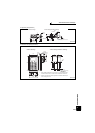
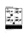
Frame Number 200L, 225S
SF-V5RU(H) , , ,
SF-V5RU
K
SF-V5RU
K1
SF-V5RU
K3
SF-V5RU
K4
Frame
No.
Mass
(kg)
Motor
Terminal Screw
Size
A B C D E F H I KA KG
KL(KP)
L M ML N XB Q QK R S T U W
U,V,W A,B,(C)
G1,G2
1 — — — 90L 24
256.5
114 90
183.6
70 62.5 198 — 53 65
220(210)
425 175 — 150 56 — —
168.5
24j6 7 4 8 M6 M4 M4
2 1 — — 100L 33 284 128 100 207 80 70
203.5
230 65 78 231 477 200 212 180 63 60 45 193 28j6 7 4 8 M6 M4 M4
3 2 1 — 112M 41 278 135 112 228 95 70 226 253 69 93 242 478 230 242 180 70 60 45 200 28j6 7 4 8 M6 M4 M4
5 3 2 — 132S 52 303 152 132 266 108 70 265 288 75 117 256 542 256 268 180 89 80 63 239
38k6
8 5 10 M6 M4 M4
7 5 3 1 132M 62 322 171 132 266 108 89 265 288 94 117 256 580 256 268 218 89 80 63 258
38k6
8 5 10 M6 M4 M4
11 7 5 2 160M 99 412 198 160 318 127 105 316 367 105 115 330 735 310 — 254 108 — — 323
42k6
8 5 12 M8 M4 M4
15 11 7 3 160L 113 434 220 160 318 127 127 316 367 127 115 330 779 310 — 298 108 — — 345
42k6
8 5 12 M8 M4 M4
18 — — —
180M
138
438.5 225.5
180 363
139.5 120.5
359 410 127 139 352 790 335 — 285 121 — —
351.5 48k6
9 5.5 14 M8 M4 M4
22 15 11 — 160
—
18 15 5 180L 200
457.5 242.5
180 363
139.5 139.5
359 410 146 139 352 828 335 — 323 121 — —
370.5 55m6
10 6 16 M8 M4 M4
30 — — 7
200L
238
483.5 267.5
200 406 159
152.5
401 — 145 487
(546)
909 390 — 361 133 — —
425.5 60m6
11 7 18 M10 M4 M4
37, 45 22, 30 18, 22 — 255
55 37 30 11, 15 225S 320 500 277 225 446 178 143 446 — 145 533
(592)
932 428 — 342 149 — — 432
65m6
11 7 18 M10 M4 M4
1K 2K 3K 5K 7K
S
T
W
U
Section AA
15
9
Frame leg viewed from above
Sliding distance
Earth (ground) terminal (M5)
Mark for earthing
(grounding)
Direction of
cooling fan wind
Exhaust
Suction
40
50
L
A
Connector (for encoder)
MS3102A20-29P
XB
FF
N
KA
B
R
A
A
D
φ27
4
C
H
KG
KL
EE
M
KP
4
12
Sliding distance
Frame leg viewed
from above
S
U
T
W
Section AA
Mark for earthing
(grounding)
Earth (ground) terminal (M5)
φ27
40
EE
M
ML
6.5
C
H
I
KG
D
KL
Connector (for encoder)
MS3102A20-29P
Direction of
cooling fan wind
Exhaust
Suction
XB
FF
N
QK
KA
QB
A
R
L
A
A
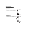
For motor (U, V, W)
For cooling fan (A, B)
Thermal protector (G1, G2)
A
B
G2G1
U
V
W
Earthing (grounding) terminal (M4)
11K 15K 18K 22K 30K 37K 45K 55K
Direction of
cooling fan wind
Mark for earthing
(grounding)
Earth (ground)
terminal (M8)
With guard
wires
Exhaust
Suction
Connector (for encoder)
MS3102A20-29P
φ56
KG
XB
FF
N
90
KA
110
BA
R
L
50
E
E
M
D
KL
8
C
H
I
A
A
Section AA
T
U
S
W
14.5
4
Sliding distance
Frame leg viewed
from above
Frame leg viewed
from above
4
18.5
Sliding distance
S
W
T
U
Section AA
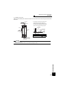
Connector (for encoder)
MS3102A20-29P
Mark for earthing
(grounding)
Earth (ground)
terminal (M12)
With guard
wires
KG
KP
L
A
Direction of
cooling fan wind
Exhaust
Suction
φ90
70
EE
M
11
C
H
D
XB
FF
N
110
KA
140
B
R
A
A
For motor (U, V, W)
For cooling fan (A, B, C) For thermal protector (G1, G2)
Earthing (grounding)
terminal (M8)
Make sure to earth the earth terminal of the frame installation foot
as well as the earth terminal in the terminal box.
0
-0.5