


302
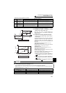
Frequency/torque setting by analog
input (terminal 1, 2, 4)
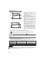
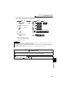
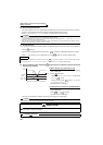
(6) Adjustment method of torque setting voltage (current) bias and gain
a) Method to adjust any point without application of a voltage (current) across terminals 1 and 5(4 and 5)
REMARKS
· An error at writing ( ) may appear if torque setting value of gain and bias are too close.
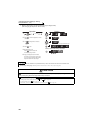
DisplayOperation
Analog voltage (current)
value (%) across terminals 1 and 5
(across terminals 4 and 5)
Flicker...Parameter setting complete!!
The value is nearly 100 (%) in
the maximum position of the
potentiometer.
CAUTION
After performing the operation in step 6, do not touch until
completion of calibration.
(Adjustment completed)
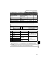
C0 to C41
setting
is enabled.
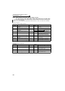
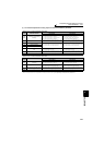
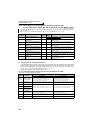
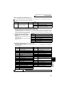
Terminal 1 input Terminal 4 input
Terminal 1 input Terminal 4 input
The parameter
number read
previously appears.
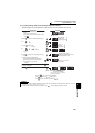
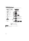
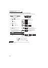
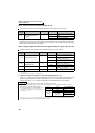
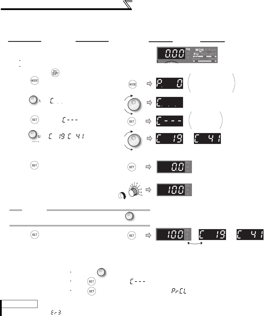
1. Confirm the RUN indicator and operation mode
indicator.
The inverter must be at a stop.
The inverter must be in the PU operation
mode.(Using )
2. Press to choose the parameter setting
mode.
3.
Turn until appears.
4. Press to display .
5.
Turn until ( ) appears.
Set to
C19 Terminal 1 gain (torque)
.
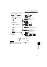
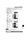
6. Press to display the analog voltage
(current) value (%).
7. Apply a 10V (20mA) voltage (current).
(Turn the external potentiometer connected
across terminals 1 and 5 (across terminals 4
and 5) to maximum (any position).)
8. Press to set.
By turning , you can read another parameter.
Press to return to the display (step 4).
Press twice to show the next parameter ( ).