


11
Installation of the inverter and enclosure
design
1
OUTLINE
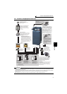
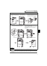
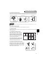
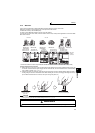
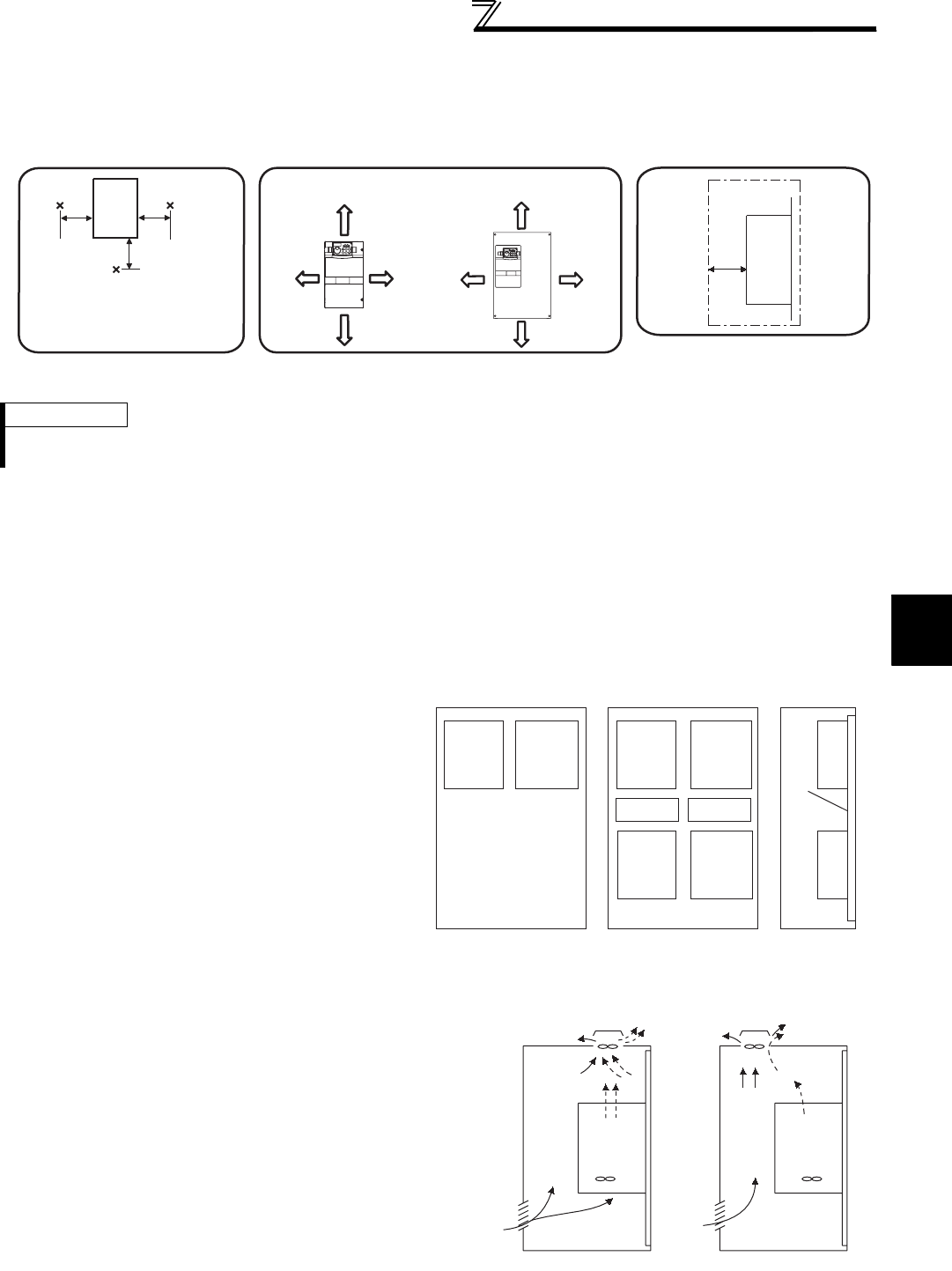
(2) Clearances around the inverter
To ensure ease of heat dissipation and maintenance, leave at least the shown clearances around the inverter. At least the
following clearances are required under the inverter as a wiring space, and above the inverter as a heat dissipation space.
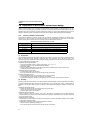
(3) Inverter mounting orientation
Mount the inverter on a wall as specified. Do not mount it horizontally or any other way.
(4) Above the inverter
Heat is blown up from inside the inverter by the small fan built in the unit. Any equipment placed above the inverter
should be heat resistant.
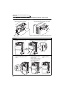
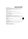
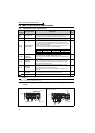
(5) Arrangement of multiple inverters
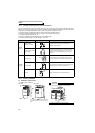
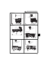
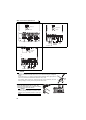
(6) Placement of ventilation fan and inverter
REMARKS
For replacing the cooling fan of the 160K or higher, 30cm of space is necessary in front of the inverter. Refer to page 431 for fan
replacement.
When multiple inverters are placed in the same
enclosure, generally arrange them horizontally as
shown in the right figure (a). When it is inevitable to
arrange them vertically to minimize space, take such
measures as to provide guides since heat from the
bottom inverters can increase the temperatures in the
top inverters, causing inverter failures.
When mounting multiple inverters, fully take caution
not to make the surrounding air temperature of the
inverter higher than the permissible value by providing
ventilation and increasing the enclosure size.
Arrangement of multiple inverters
Heat generated in the inverter is blown up from the bottom of
the unit as warm air by the cooling fan. When installing a
ventilation fan for that heat, determine the place of ventilation
fan installation after fully considering an air flow. (Air passes
through areas of low resistance. Make an airway and airflow
plates to expose the inverter to cool air.)
Placement of ventilation fan and inverter
ClearancesSurrounding air temperature and humidity
Measurement
position
Measurement
position
Inverter
Leave enough clearances and take
cooling measures.
55K or lower 75K or higher
5cm
5cm
5cm
10cm or more
20cm or more
20cm or more
10cm or more
5cm
or more *
5cm
or more *
10cm
or more
10cm
or more
Temperature:
-10°C to 50°C
Ambient humidity:
90% RH maximum
(front)
*1cm or more for 3.7K or lower
Clearances (side)
Inverter
5cm
or more
*
*1cm or more for 3.7K or lower
Guide Guide
Enclosure Enclosure
Guide
(a) Horizontal arrangement
(b) Vertical arrangement
Inverter
Inverter
Inverter
Inverter
Inverter
Inverter
Inverter Inverter
<Good example> <Bad example>