


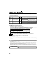
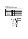

292
Frequency/torque setting by analog
input (terminal 1, 2, 4)
4.21.4 Response level of analog input and noise elimination
(Pr. 74, Pr. 822, Pr. 826, Pr. 832, Pr. 836, Pr. 849)
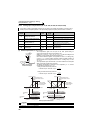
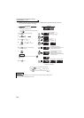
(1) Block diagram
Response level and stability of frequency reference command and torque reference command by analog input
(terminal 1, 2, 4) signal can be adjusted.
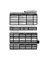
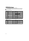
Parameter
Number
Name
Initial
Value
Setting
Range
Description
74 Input filter time constant 1 0 to 8
The primary delay filter time constant for the analog input
can be set. A larger setting results in slower response.
822 Speed setting filter 1 9999
0 to 5s
Set the time constant of the primary delay filter relative to
the external speed command (analog input command).
9999 Pr. 74 used
826 Torque setting filter 1 9999
0 to 5s
Set the time constant of the primary delay filter relative to
the external torque command (analog input command).
9999 Pr. 74 used
832 Speed setting filter 2 9999 0 to 5s, 9999 Second function of Pr. 822 (valid when RT terminal is on)
836 Torque setting filter 2 9999 0 to 5s, 9999 Second function of Pr. 826 (valid when RT terminal is on)
849
Analog input offset
adjustment
100% 0 to 200%
This function provides speed command by analog input
(terminal 2) with offset. Motor rotation due to noise, etc.
by analog input can be avoided at zero speed command.
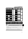
Terminal 1 (2, 4 ) input
RT-OFF
RT-ON
Pr. 822 = 9999
Pr. 822 9999
Pr. 826 = 9999
Pr. 826 9999
Pr. 832 = 9999
Pr. 832 9999
Pr. 836 = 9999
Pr. 836 9999
Pr. 836
Pr. 832
Pr. 826
Pr. 74
Pr. 822
Pr. 74
Speed command
Torque command