252
Monitor display and monitor output signal
⋅ To display the machine speed, set in Pr. 37 the machine speed for operation with frequency set in Pr. 505.
For example, when Pr. 505 = "60Hz" and Pr. 37 = "1000", "1000" is displayed on the running speed monitor when the
running frequency is 60Hz. When running frequency is 30Hz, "500" is displayed.
⋅ When displaying the motor speed, set the number of motor poles (2, 4, 6, 8, 10) or number of motor poles + 100
(102, 104, 106, 108, 110) in Pr. 144.
⋅ The Pr. 144 setting is automatically changed if the number of motor poles is set in Pr. 81 Number of motor poles. The Pr.
81 setting is not automatically changed even if the setting of Pr. 144 is changed.
Example 1)When the initial value of Pr. 81 is changed to "2" or "12", the Pr. 144 setting changes from "4" to "2".
Example 2)When Pr. 144 = "104", setting "2" in Pr. 81 changes the Pr. 144 setting from "104" to "102".
⋅ When "1, or 11" is set in Pr. 811, the setting increments of speed setting from the PU, speed setting from RS-485
communication or communication options (other than FR-A7ND, FR-A7NL) and running speed monitor is 0.1r/min.
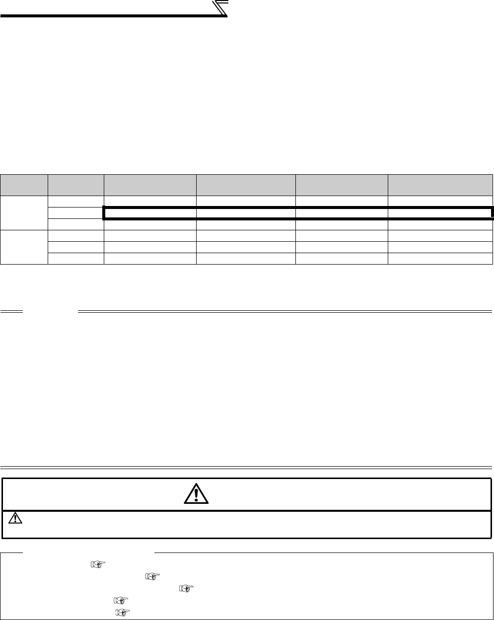
⋅ A combination of the Pr.37 and Pr. 144 settings determines the setting increment as shown in the table below.
(Initial value are outlined with bold borders.)
Pr. 37
Setting
Pr. 144
Setting
Output Frequency
Monitor
Set Frequency
Monitor
Running Speed
Monitor
Frequency Setting
Parameter Setting
0
(initial
value)
0 0.01Hz 0.01Hz 1r/min
*1 0.01Hz
2 to 10 0.01Hz 0.01Hz 1r/min
*1 0.01Hz
102 to 110 1r/min
*1 1r/min *1 1r/min *1 1r/min *1
1 to 9998
0 0.01Hz 0.01Hz 1 (Machine speed
*1) 0.01Hz
2 to 10 1 (Machine speed
*1) 1 (Machine speed *1) 1 (Machine speed *1) 1 (Machine speed *1)
102 to 110 0.01Hz 0.01Hz 1r/min
*1 0.01Hz
*1 Motor speed r/min conversion formula............ frequency × 120/number of motor poles (Pr. 144)
Machine speed conversion formula...................Pr. 37 × frequency/Pr. 505
For Pr. 144 in the above formula, the value is "Pr. 144 - 100" when "102 to 110" is set in Pr. 144 and the value is "4" when Pr. 37 = 0 and Pr. 144 = 0.
Pr. 505 is always set as frequency (Hz).
CAUTION
⋅ The inverter's output frequency is displayed as synchronous speed under V/F control. The displayed value is "actual motor
speed" + "motor slip." This display changes to the actual speed (estimated value calculated based on the motor slip) when the
Advanced magnetic flux vector control or Real sensorless vector control is selected, and actual speed from the encoder when
encoder feedback control or vector control is performed.
⋅ When the running speed display is selected at the setting of Pr. 37 = "0" and Pr. 144 = "0", the monitor display is provided on the
assumption that the number of motor poles is 4. (1800r/min is displayed at 60Hz)
⋅ Refer to Pr. 52 when you want to change the PU main monitor (PU main display).
⋅ Since the panel display of the operation panel (FR-DU07) is 4 digits in length, the monitor value of more than "9999" is
displayed "----".
⋅ After setting the running speed in 0.1r/min increments (Pr. 811 = "1, 11"), changing the setting increments to 1r/min increments
(Pr. 811 = "0, 10") changes the speed resolution from 0.1r/min to 0.3r/min (four poles), which may round down 0.1r/min
increments.
⋅ When the machine speed is displayed on the FR-PU04/FR-PU07, do not change the speed by using an up/down key in the
state where the set speed exceeding 65535 is displayed. The set speed may become arbitrary value.
⋅ When an optional FR-A7ND or FR-A7NL card is mounted, frequency is displayed regardless of Pr. 37 and Pr. 144 setting.
CAUTION
Make sure that the settings of the running speed and number of motor poles are correct. Otherwise, the motor
might run at extremely high speed, damaging the machine.
♦ Parameters referred to ♦
Pr. 1 Maximum frequency Refer to page 157
Pr. 52 DU/PU main display data selection Refer to page 253
Pr. 80 Motor capacity, Pr. 81 Number of motor poles Refer to page 148
Pr. 800 Control system selection Refer to page 92
Pr. 811 Set resolution switchover Refer to page 100


