


3
Inverter and peripheral devices
1
OUTLINE
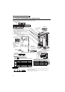
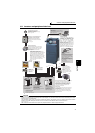
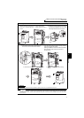
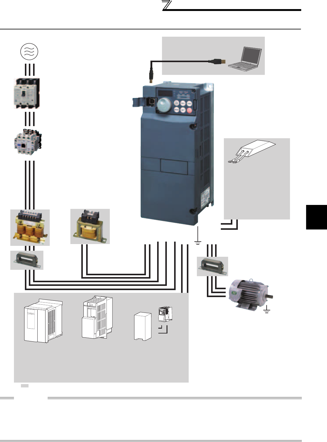
1.2 Inverter and peripheral devices
CAUTION
·
Do not install a power factor correction capacitor, surge suppressor or radio noise filter on the inverter output side. This will cause the
inverter to trip or the capacitor, and surge suppressor to be damaged. If any of the above devices are connected, immediately remove them.
· Electromagnetic wave interference
The input/output (main circuit) of the inverter includes high frequency components, which may interfere with the communication
devices (such as AM radios) used near the inverter.
In this case, set the EMC filter valid to minimize interference.
(Refer to page 15)
· Refer to the instruction manual of each option and peripheral devices for details of peripheral devices.
Line noise filter
Line noise filter
Motor
Devices connected to the output
P/+
P/+
PR
PR
AC reactor
(FR-HAL)
DC reactor (FR-HEL)
Install a line noise filter to
reduce the electromagnetic
noise generated from the
inverter.
Effective in the range from
about 1MHz to 10MHz. A wire
should be wound four turns at
a maximum.
Power supply harmonics can
be greatly suppressed.
Install this as required.
Great braking capability is obtained.
Install this as required.
The regenerative braking
capability of the inverter can
be exhibited fully.
Install this as required.
Three-phase AC power supply
Use within the permissible power supply
specifications of the inverter.
USB connector
A personal computer and an inverter can
be connected with a USB (Ver1. 1) cable.
Moulded case circuit breaker (MCCB) or
earth leakage current breaker (ELB),
fuse
The breaker must be selected carefully
since an in-rush current flows in the inverter
at power on.
Magnetic contactor (MC)
Install the magnetic contactor to ensure safety.
Do not use the magnetic contactor for frequent
starting/stopping of the inverter. Doing so will
cause the inverter life to be shortened.
Do not install a power factor correction capacitor,
surge suppressor or radio noise filter on the output
side of the inverter. When installing a moulded case
circuit breaker on the output side of the inverter,
contact each manufacturer for selection of the
moulded case circuit breaker.
R/L1 S/L2 T/L3
P1P/+ N/-P/+
UW
P/+
PR
V
High power factor converter
(FR-HC
*1
, MT-HC
*2
)
Power regeneration
common converter (FR-CV
*1
)
Power regeneration
converter (MT-RC
*2
)
Resistor unit
(FR-BR
*1
, MT-BR5
*2
)
Brake unit
(FR-BU2
*3
, FR-BU
*1
, MT-BU5
*2
)
(FR-BLF)
Earth (Ground)
Earth (Ground)
To prevent an electric shock, always earth (ground) the
motor and inverter.
For reduction of induction noise from the power line of
the inverter, it is recommended to wire the earthing
(grounding) cable by returning it to the earth (ground)
terminal of the inverter.
Earth
(Ground)
: Install these options as required.
The 55K or lower has
a built-in common
mode choke.
For the 75K or higher, a
DC reactor is supplied.
Always install the reactor.
*1 Compatible with the 55K or lower.
*2 Compatible with the 75K or higher.
*3 Compatible with all capacities.
High-duty brake resistor
(FR-ABR
*4
)
Braking capability of the inverter built-
in brake can be improved. Remove
the jumper across terminal PR-PX
when connecting the high-duty brake
resistor. (7.5K or lower)
Always install a thermal relay when
using a brake resistor whose capacity
is 11K or higher.
*4 Compatible with the 22K or lower.
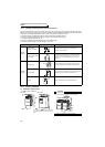
Reactor (FR-HAL, FR-HEL option)
Install reactors to suppress harmonics and to
improve the power factor. An AC reactor (FR-HAL)
(option) is required when installing the inverter
near a large power supply system (1000kVA or
more).
The inverter may be damaged if you do not use a
reactor. Select a reactor according to the model.
Remove the jumpers across terminals P/+ - P1 to
connect the DC reactor to the 55K or lower.
(Refer to page 442)
(Refer to page 5)
(Refer to page 360)
(Refer to page 61)
(Refer to page 60 )
Inverter (FR-A700)
The life of the inverter is influenced by
surrounding air temperature. The
surrounding air temperature should be as
low as possible within the permissible
range. This must be noted especially
when the inverter is installed in an
enclosure. (Refer to page 8.)
Wrong wiring might lead to damage of the
inverter. The control signal lines must be
kept fully away from the main circuit to
protect them from noise.(Refer to page 14)
Refer to page 15 for the built-in noise filter.
(Refer to page
40)