


1
CONTENTS
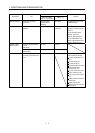
1. FUNCTIONS AND CONFIGURATION 1 - 1 to 1 -12
1.1 Summary .................................................................................................................................................. 1 - 1
1.2 Servo amplifier standard specifications................................................................................................... 1 - 3
1.3 Function list .............................................................................................................................................. 1 - 4
1.4 Model code definition ............................................................................................................................... 1 - 5
1.5 Combinations of servo amplifiers and direct drive motor........................................................................ 1 - 5
1.6 Parts identification .................................................................................................................................... 1 - 6
1.7 Configuration including auxiliary equipment............................................................................................ 1 - 9
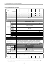
2. DIRECT DRIVE MOTOR 2 - 1 to 2 -34
2.1 Rating plate .............................................................................................................................................. 2 - 1
2.2 Parts identification.................................................................................................................................... 2 - 1
2.3 Installation ................................................................................................................................................ 2 - 2
2.3.1 Equipment configuration ................................................................................................................... 2 - 3
2.3.2 Installation orientation ....................................................................................................................... 2 - 4
2.3.3 Load remove precautions ................................................................................................................. 2 - 4
2.3.4 Permissible load for the rotor ............................................................................................................ 2 - 4
2.3.5 Protection from oil and water ............................................................................................................ 2 - 5
2.3.6 Inspection .......................................................................................................................................... 2 - 6
2.3.7 Life ..................................................................................................................................................... 2 - 6
2.3.8 Machine accuracies .......................................................................................................................... 2 - 7
2.3.9 Flange surface size ........................................................................................................................... 2 - 7
2.4 Connectors used for direct drive motor wiring ........................................................................................ 2 - 8
2.4.1 Selection of connectors..................................................................................................................... 2 - 8
2.4.2 Wiring connectors (Connector configurations A
B C D E F) .............................................. 2 - 9
2.4.3 Connector outline drawings ............................................................................................................. 2 -11
2.5 TM-RFM series direct drive motor..........................................................................................................2 -15
2.5.1 Model code definition .......................................................................................................................2 -15
2.5.2 Specification list................................................................................................................................2 -16
2.5.3 Torque characteristic........................................................................................................................ 2 -19
2.5.4 Outline dimension drawings.............................................................................................................2 -20
2.5.5 Connection of servo amplifier and direct drive motor .....................................................................2 -32
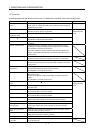
3. SIGNALS AND WIRING 3 - 1 to 3 -12
3.1 Precautions for this chapter ..................................................................................................................... 3 - 2
3.2 Input power supply circuit ........................................................................................................................ 3 - 2
3.2.1 Selection example of wires ...............................................................................................................3 - 3
3.2.2 Connection example ......................................................................................................................... 3 - 4
3.3 I/O signal connection example ................................................................................................................3 - 7
3.4 Connector and signal arrangements ....................................................................................................... 3 - 9
3.5 Internal connection diagram ...................................................................................................................3 -10
3.5.1 Incremental system ..........................................................................................................................3 -10
3.5.2 Absolute position detection system ................................................................................................. 3 -11