


2. DIRECT DRIVE MOTOR
2 - 18
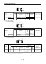
Note 1. When the power supply voltage drops, the output and the rated speed cannot be guaranteed.
2. If the load inertia moment ratio exceeds the indicated value, please contact your local sales office.
3. Note that the power supply equipment capacity will vary according to the power supply impedance. This value assumes that the
power factor improving AC reactor or the power factor improving DC reactor is not used.
4. Optional battery (MR-J3BAT) and absolute position storage unit (MR-BTAS01) are required for absolute position detection system.
5. Connectors and gap between rotor and stator are excluded.
6. In the environment where the direct drive motor is exposed to oil mist, oil and/or water, a standard specification direct drive motor
may not be usable. Take dustproof and waterproof measures on the machine side.
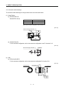
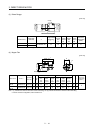
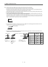
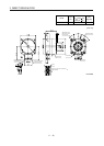
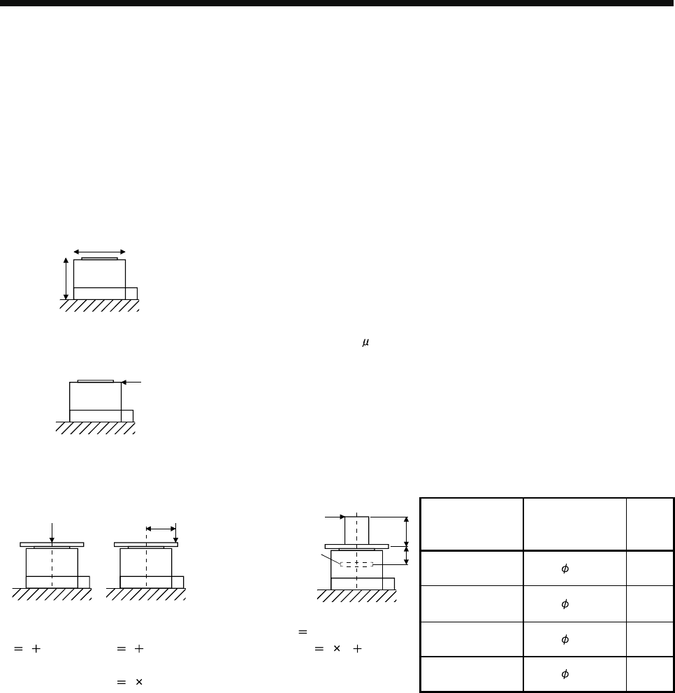
7. The vibration direction is shown in the diagram. The numeric value indicates the maximum value of the component (commonly the
bracket in the opposite direction of the direct drive motor rotor (output shaft)). Fretting of the bearing occurs easily when the motor
stops, so maintain vibration to approximately one-half of the allowable value.
X
Y
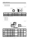
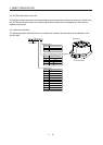
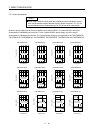
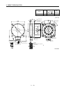
8. V-10 indicates that the amplitude of a single direct drive motor is 10 m or less. The following figure shows the direct drive motor
installation position for measurement and the measuring position.
Measuring position
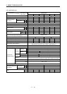
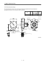
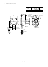
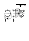
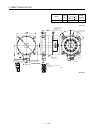
9. The following is calculation examples of axial and moment loads to the rotor (output shaft). The axial and moment loads must be
maintained equal to or below the permissible value.
Direct drive motor
Motor outer
diameter [mm]
(Frame dimensions)
Dimen-
sion A
[mm]
TM-RFM002C20 to
006C20
130 19.1
F (Outer force)
L
F (Outer force)
L
F (Outer force)
A
Bearing
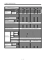
TM-RFM006E20 to
018E20
180 20.2
Axial load
F load mass
Axial load
load mass
Moment load
F (L A)
TM-RFM012G20
to 072G20
230 24.4
Axial load
F load mass
Moment load
F L
TM-RFM040J10 to
240J10
330 32.5