


3. SIGNALS AND WIRING
3 - 6
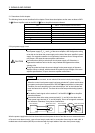
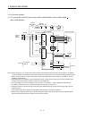
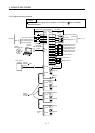
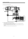
(3) MR-J3-500B-RJ080W
MC (Note 8)
MCCB
L1
L
2
L3
3-phase
200 to
230VAC
Servo amplifier
C
P
U
V
W
TE1
PE
L
11
L
21
TE2
Direct drive motor
U
V
W
M
Motor
Encoder
CN2
Encoder cable
(Note 5)
P1
P
2
N
TE3
(Note 1)
(Note 2)
Built-in
regenerative
resistor
(Note 3)
Malfunction
RA1
Controller
forced stop
EM1
ALM
DICOM
DOCOM
24VDC
Malfunction
(Note 3)
DOCOM
CN3 CN3
(Note 4)
(Note 4)
RA1
Forced stop
(Note 6)
RA2
OFF
MC
ON
MC
SK
(Note 6)
Forced stop
(Note 7)
Note 1. Always connect P1 and P2. (Factory-wired.) When using the power factor improving DC reactor, refer to chapter 11 of the MR-J3-
B Servo Amplifier Instruction Manual. Use either the power factor improving DC reactor or the power factor improving AC reactor.
2. When using the regenerative option, refer to chapter 11 of the MR-J3-
B Servo Amplifier Instruction Manual.
3. If deactivating output of malfunction (ALM) with parameter change, configure up the power supply circuit which switches off the
magnetic contactor after detection of alarm occurrence on the controller side.
4. For sink I/O interface. For source I/O interface, refer to section 3.7.3 of the MR-J3-
B Servo Amplifier Instruction Manual.
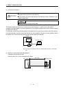
5. For details of connection of the servo amplifier and direct drive motor, refer to section 2.5.5.
6. Configure the circuit to shut down the main circuit power supply simultaneously with the turn off of forced stop (EM1) using the
external sequence.
7. This connector detects speed, position and temperature of the direct drive motor. (Refer to chapter 9.)
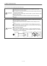
8. Be sure to use a magnetic contactor with an operation delay time of 80ms or less. The operation delay time is the time interval
between current being applied to the magnetic coil until closure of contacts.