


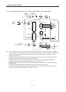
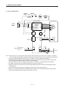
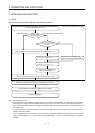
3. SIGNALS AND WIRING
3 - 8
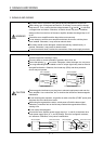
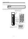
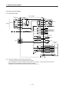
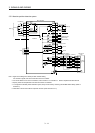
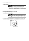
Note 1 To prevent an electric shock, always connect the protective earth (PE) terminal ( ) of the servo amplifier to the protective earth
(PE) of the cabinet.
2. Connect the diode in the correct direction. If it is connected reversely, the servo amplifier will be faulty and will not output signals,
disabling the forced stop (EM1) and other protective circuits.
3. If the controller does not have an forced stop (EM1) function, always install a forced stop switch (Normally closed contact).
4. When starting operation, always turn on the forced stop (EM1). (Normally closed contact) By setting "
1 " in the parameter
No.PA04 of the servo amplifier, the forced stop (EM1) can be made invalid.
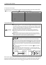
5. Use MRZJW3-SETUP 221E (Software version is C2 or later). (Refer to section 11.8 of the MR-J3-
B Servo Amplifier Instruction
Manual)
6. Use SSCNET
cables listed in the following table.
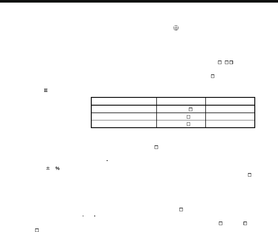
Cable Cable model name Cable length
Standard cord inside panel MR-J3BUS M 0.15m to 3m
Standard cable outside panel MR-J3BUS M-A 5m to 20m
Long-distance cable MR-J3BUS M-B 30m to 50m
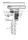
7. The wiring of the second and subsequent axis is omitted.
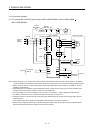
8. Up to 16 axes may be connected. Refer to section 3.13 of the MR-J3-
B Servo Amplifier Instruction Manual for setting of axis
selection.
9. Make sure to put a cap on the unused CN1A
CN1B.
10. Supply 24VDC
10 150mA current for interfaces from the outside. 150mA is the value applicable when all I/O signals are used.
The current capacity can be decreased by reducing the number of I/O points. Refer to section 3.7.2 (1) of the MR-J3-
B Servo
Amplifier Instruction Manual that gives the current value necessary for the interface.
11. Malfunction (ALM) turns on in normal alarm-free condition (Normally closed contacts).
12. The pins with the same signal name are connected in the servo amplifier.
13. The signal can be changed by parameter No.PD07, PD08, PD09.
14. For sink I/O interface. For source I/O interface, refer to section 3.7.3 of the MR-J3-
B Servo Amplifier Instruction Manual.
15. Devices can be assigned for DI1
DI2 DI3 with controller setting. For devices that can be assigned, refer to the controller
instruction manual. The assigned devices are for the Q173DCPU, Q172DCPU, Q170MCPU, LD77MH
,QD74MH and
QD75MH
.
16. Electromagnetic brake interlock (MBR) is useful when setting up an external brake system.