


9. OPTIONS FOR DIRECT DRIVE SERVO
9 - 8
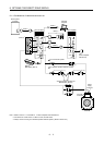
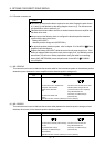
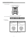
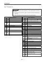
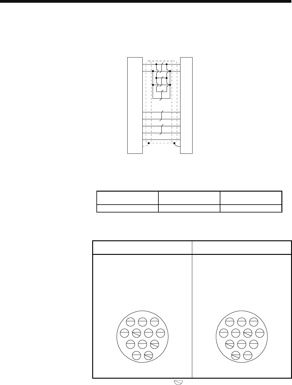
2) Internal wiring diagram
When the distance between the servo amplifier and the
direct drive motor is within 20m (Note)
c) For CN2 connector
d) For absolute position
storage unit connector
P5
LG
1
2
MR
MRR
3
4
6
9
5
7
8
10
LG
MR
MRR
P5
THM1THM1
116 THM2THM2
29 BAT
5FG
BAT
PlateSD
Note. For the cable of 20m or longer, contact your local sales office.
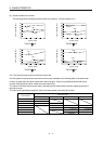
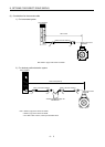
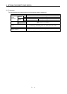
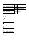
Refer to the following table for the required wires to fabricate the encoder cable.
Core size [mm
2
]
Conductor resistance of
one core [Ω/km]
Cable OD [mm]
0.25 63.6 or less 8.2
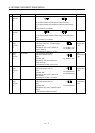
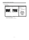
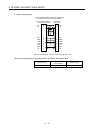
(c) Encoder cable C)
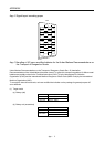
1) Connector details
e) For absolute position storage unit
connector
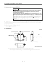
f) For encoder connector
Straight plug: RM15WTPZ-12P(72)
Cord clamp: JR13WCCA-8(72)
(Hirose Electric)
Recommended cable:
20276 VSVPAWG#23×6P
KB-0492 (Note 2)
(Bando Densen)
1
MR
2
MRR
3
5
LG
4
BAT
7
6
12
THM1
98
P5
10
11
FG
THM2
VB
View seen from the wiring side. (Note 1)
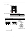
Straight plug: RM15WTPZK-12S
Cord clamp: JR13WCCA-8(72)
(Hirose Electric)
Recommended cable:
20276 VSVPAWG#23×6P
KB-0492 (Note 2)
(Bando Densen)
1
MR
2
MRR
3
5
LG
4
BAT
7
6
12
THM1
9 8
P5
10
11
FG
THM2
VB
View seen from the wiring side. (Note 1)
Note 1. Keep open the pin shown with .
2. Purchase from Toa Electric Industry Co. Ltd., Nagoya Branch