


2. DIRECT DRIVE MOTOR
2 - 33
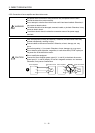
(1) Connection instructions
CAUTION
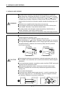
To avoid a malfunction, connect the power supply phases (U, V, and W) of the servo
amplifier and the direct drive motor correctly.
Do not connect AC power supply directly to the direct drive motor. Otherwise, it may
cause a malfunction.
POINT
Refer to chapter 9 for the encoder cable.
This section explains the connection of the direct drive motor power (U, V, and W). Use of the optional
connector is recommended for connection between the servo amplifier and direct drive motor. Refer to chapter 9
for details of the options.
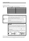
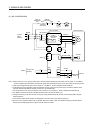
For grounding, connect the grounding lead wire from the direct drive motor to the protective earth (PE) terminal
of the servo amplifier, and then connect the wire from the servo amplifier to the ground via the protective earth of
the cabinet. Do not connect the wire directly to the protective earth of the cabinet.
Servo
amplifier
Cabinet
Direct drive motor
PE terminal
(Note)
Note. The number of PE terminals of the servo amplifier differs depending on the amplifier
type.
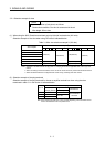
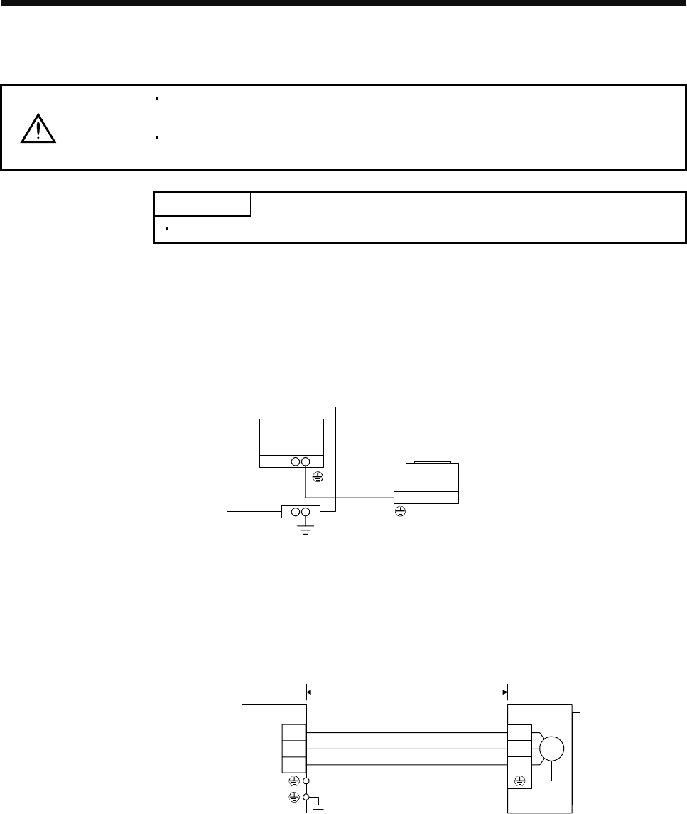
(2) Direct drive motor power cable wiring diagram
Fabricate a cable as shown below.
Refer to section 3.2.1 for the wires used for the cable.
U
V
W
U
V
W
Direct drive motorServo amplifier
30m or less
M