


3. SIGNALS AND WIRING
3 - 3
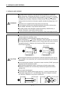
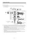
3.2.1 Selection example of wires
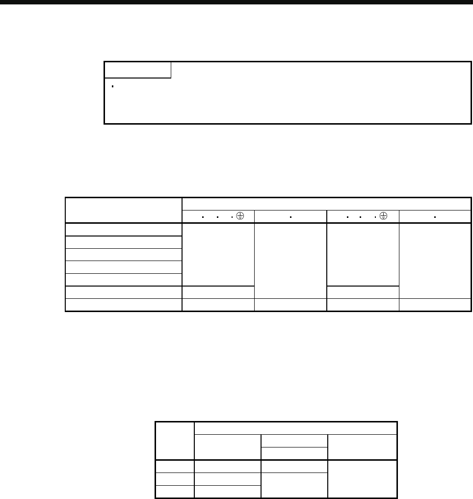
POINT
Selection condition of wire size is as follows.
Construction condition: One wire is constructed in the air
Wire length: 30m or less
(1) When using the 600V Grade heat-resistant polyvinyl chloride insulated wire (HIV wire)
Selection example of wire size when using HIV wires is indicated below.
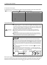
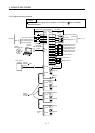
Table 3.1 Wire size selection example 2 (HIV wire)
Wires [mm
2
] (Note 1, 3)
Servo amplifier
L
1 L2 L3 L11 L21 UV W PC
MR-J3-20B-RJ080W
MR-J3-40B-RJ080W
MR-J3-60B-RJ080W 2(AWG14) 1.25(AWG16)
MR-J3-70B-RJ080W
1.25(AWG16)
2(AWG14)
MR-J3-100B-RJ080W
MR-J3-350B-RJ080W 3.5(AWG12) 3.5(AWG12)
MR-J3-500B-RJ080W (Note 2) 5.5(AWG10): a 1.25(AWG16): b 5.5(AWG10): a 2(AWG14): c
Note 1. Alphabets in the table indicate crimping tools. For crimping terminals and applicable tools, refer to (3) in this
section.
2. When connecting to the terminal block, be sure to use the screws which are provided with the terminal block.
3. Wires are selected based on the highest rated current among combining direct drive motors.
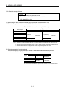
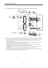
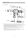
(2) Selection example of crimping terminals
Selection example of crimping terminals for the servo amplifier terminal box when using the wires
mentioned in table 3.1 in this section is indicated below.
Servo amplifier side crimping terminals
Symbol Applicable tool
(Note)
Crimping terminal
Body
Manufacturer
a FVD5.5-4 YNT-1210S
b FVD2-M3
c FVD2-4
YNT-1614
Japan Solderless
Terminals
Note. Some crimping terminals may not be mounted depending on the size. Make sure to
use the recommended ones or equivalent ones.