


APPENDIX
App. - 2
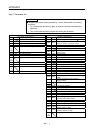
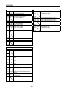
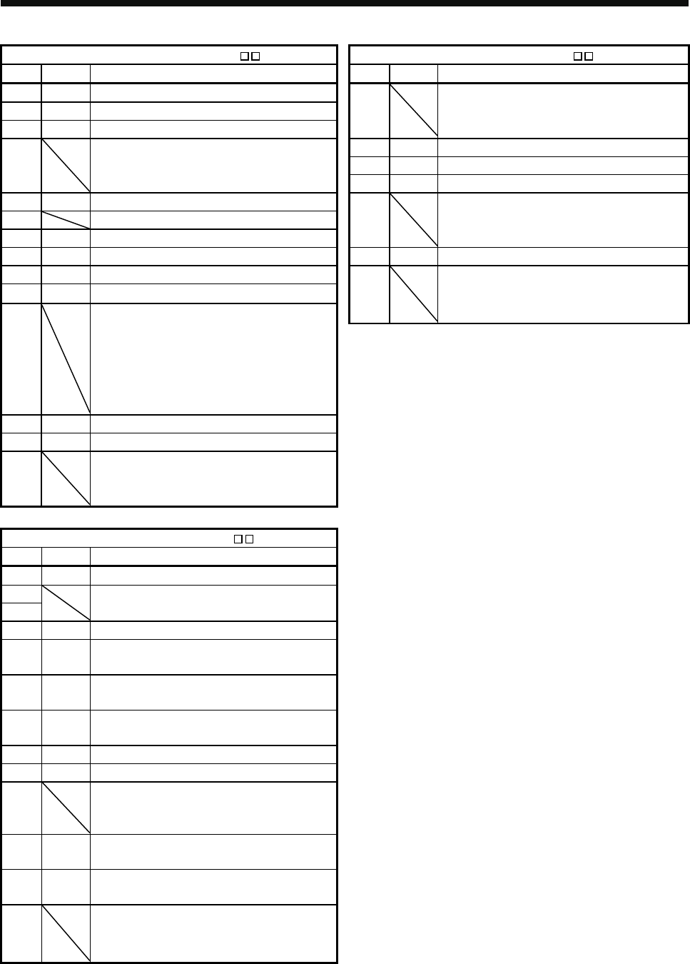
Extension setting parameters (PC ) I/O setting parameters (PD )
No. Symbol Name No. Symbol Name
PC01 *ERZ Error excessive alarm level
PD01 For manufacturer setting
PC02 MBR Electromagnetic brake sequence output
to
PC03 *ENRS Encoder output pulses selection
PD06
PC04 For manufacturer setting
PD07 *D01 Output signal device selection 1 (CN3-13)
to
PD08 *D02 Output signal device selection 2 (CN3-9)
PC06
PD09 *D03 Output signal device selection 3 (CN3-15)
PC07 ZSP Zero speed
PD10 For manufacturer setting
PC08 For manufacturer setting
to
PC09 MOD1 Analog monitor 1 output
PD13
PC10 MOD2 Analog monitor 2 output
PD14 *DOP3 Function selection D-3
PC11 MO1 Analog monitor 1 offset
PD15 For manufacturer setting
PC12 MO2 Analog monitor 2 offset
to
PC13 For manufacturer setting
PD32
to
PC19
PC20 *COP7 Function selection C-7
PC21 *BPS Alarm history clear
PC22 For manufacturer setting
to
PC32
Special setting parameters (PS )
No. Symbol Name
PS01 **LIT1 Special function selection 1
PS02 For manufacturer setting
PS03
PS04 *LIT2 Special function selection 2
PS05 LB1
Servo control position deviation error detection
level
PS06 LB2
Servo control speed deviation error detection
level
PS07 LB3
Servo control torque deviation error detection
level
PS08 *LIT3 Special function selection 3
PS09 LPWM Magnetic pole detection voltage level
PS10 For manufacturer setting
to
PS16
PS17 LTSTS
Minute position detection method function
selection
PS18 IDLV
Minute position detection method identification
signal amplitude
PS19 For manufacturer setting
to
PS32