


MNA1MLSDM00EN, V2.01, 07.2009
PAS4•S 1 Introduction
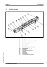
Portal axes with ball screw drive 13
Distance between carriages
3)
Up to 999 = in mm (xxx = with a single
carriage)
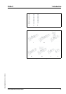
PAS 4 2 S B D 1200 C 1 B A
100 S/23G0V03
Axis drive interface
See Figure 1.3
S = With motor mounting or motor
adapter mounting
D = With shaft extension
N = Support axis
PAS 4 2 S B D 1200 C 1 B A 100
S /23G0V03
Gearbox / motor interface
1 = With motor, without gearbox (select
motor type)
2 = With motor, with gearbox (select
motor/gearbox type)
3 = Without motor, with gearbox (select
motor/gearbox type)
4 = Without motor, without gearbox
(select motor/gearbox type)
X = Without motor, without gearbox (with-
out select motor/gearbox selection)
PAS 4 2 S B D 1200 C 1 B A 100 S /
2 3G 0 V0 3
Gearboxes
0G = Planetary gear - PLE 40
1G = Planetary gear - PLE 60
3G = Planetary gear - PLE 80
5G = Planetary gear - PLE 120
0A = Planetary gear - WPLE 40
1A = Planetary gear - WPLE 60
3A = Planetary gear - WPLE 80
5A = Planetary gear - WPLE 120
7G = Planetary gear - PLS 70
8G = Planetary gear - PLS 90
9G = Planetary gear - PLS 115
YY = Third-party gearbox without mount-
ing by Schneider Electric (gearbox draw-
ing required)
ZZ = Third-party gearbox with mounting
by Schneider Electric (gearbox must be
provided)
XX = No gearbox
PAS 4 2 S B D 1200 C 1 B A 100 S / 2
3G 0V03
Mounting direction gearbox
(with clamping hub mounting screw of
adapter plate)
0 = 0 a'clock
3 = 3 a'clock
6 = 6 a'clock
9 = 9 a'clock
X = No gearbox
PAS 4 2 S B D 1200 C 1 B A 100 S / 2 3G 0 V0 3
Example PAS 4 2 S B D 1200 C 1 B A 100 S / 2 3G 0 V0 3