


MNA1MLSDM00EN, V2.01, 07.2009
PAS4•S 4 Installation
Portal axes with ball screw drive 49
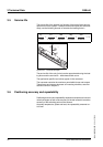
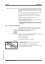
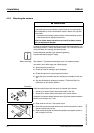
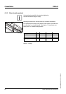
Alignment for running accuracy Due to the manufacturing process of the extruded profiles, a linear axis
has a certain tolerance in terms in straightness and twist. The deviations
are generally well within the specifications of EN 12020-2 in the case of
the product.
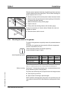
Perform the following lateral alignment procedure for running accuracy.
The mounting surface must be machined smooth and flat.
̈ First, slightly tighten the screws of the slot nuts or the clamping
claws.
̈ Provide a reference plane alongside the linear axis.
̈ Place a dial gauge onto the carriage.
̈ Move the carriage and record the deviation with reference to the ref-
erence plane over the entire stroke.
̈ Correct the deviations by lateral alignment of the linear axis and by
tightening the screws appropriately. Observe the standard tighten-
ing torques 47.
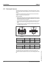
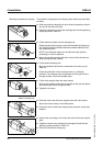
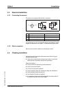
4.2.3 Mounting the contact plate
A contact plate must be mounted to the carriage for the inductive sen-
sors. Fastening threads are located at both sides of the carriage.
Unless otherwise specified, the standard tightening
torques indicated on page 47 apply.
Before mounting See chapter 7 "Accessories and spare parts", subchapter 7.5 "Sensors
and additional parts" for suitable contact plates.
You need a set of Allen keys.
̈ Clean all parts you will use.
̈ Check all parts for damage; repair damages.
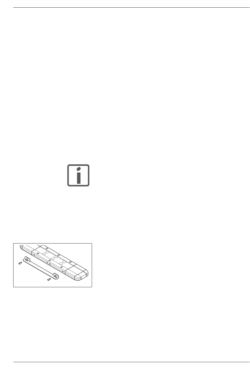
Procedure
̈ For mounting, select the side of the carriage that will be easily
accessible for service.
̈ Screw the contact plate to the carriage with M4 screws.
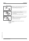
̈ Align the contact plate in parallel with the carriage so as to have the
same switching distance on both sides.