


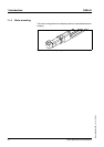
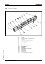
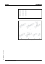

14 Portal axes with ball screw drive
1 Introduction PAS4•S
MNA1MLSDM00EN, V2.01, 07.2009
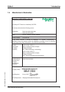
Motor / gearbox interface
V6 = Stepper motors BRS 364 / BRS 366
V8 = Stepper motors BRS 368
V9 = Stepper motors BRS 397 / BRS 39A
V0 = Stepper motors BRS 39B
V1 = Stepper motors BRS 3AC / BRS
3AD
I6 = ILS..571; ILS..572 with stepper
motor
I7 = ILS..573 with stepper motor
I9 = ILS..851; ILS..852 with stepper
motor
I8 = ILS..853 with stepper motor
E7 = DC brushless ILExx66
S6 = Servo motors SER 36• / BRH 057
S9 = Servo motors SER 39• / BRH 085
S1 = Servo motors SER 311• / BRH 110
A6 = ILA..57 with servo motors
H5 = Servo motors BSH 055•
H7 = Servo motors BSH 0701 / BSH
0702 / BMH 0701 / BMH 0702
H8 = Servo motors BSH 0703 / BMH
0703
H1 = Servo motors BSH 1001 / BSH
1002 / BSH 1003; BMH 1001 / BMH 1002
/ BMH 1003
H4 = Servo motors BSH 1004
H2 = Servo motors BSH 1401 / BSH
1402 / BSH 1403 / BSH 1404 / BMH
1401 / BMH 1402 / BMH 1403
YY = Third-party motor without mounting
by Schneider Electric (motor drawing
required)
ZZ = Third-party motor with mounting by
Schneider Electric (motor drawing
required; motor must be provided)
XX = No motor
PAS 4 2 S B D 1200 C 1 B A 100 S / 2 3G 0
V0 3
Mounting direction motor with refer-
ence to power connection
(with clamping hub mounting screw of
adapter plate)
0 = 0 a'clock
3 = 3 a'clock
6 = 6 a'clock
9 = 9 a'clock
X = No motor
PAS 4 2 S B D 1200 C 1 B A 100 S / 2 3G 0 V0
3
1) With 100 mm cable with connector at one end, other versions and extension cables as accessories
2) Only carriages of the same type are possible.
3) Minimum distance between 2 carriages: see dimensional drawings
Example PAS 4 2 S B D 1200 C 1 B A 100 S / 2 3G 0 V0 3