


48 Portal axes with ball screw drive
4 Installation PAS4•S
MNA1MLSDM00EN, V2.01, 07.2009
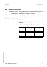
4.2.2 Mounting the linear axis
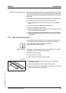
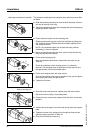
Only mount the linear axis using the T slots at the axis body. To do so,
use clamping claws (lateral fastening) or slot nuts (bottom or lateral fas-
tening).
A selection of suitable clamping claws and slot nuts can be found in
chapter 7 "Accessories and spare parts".
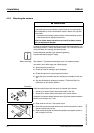
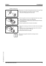
Note the following:
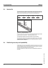
• When using motors with a cross section greater than the cross sec-
tion than the axis body, the axis must be supported or the mounting
surface must be cut out as required.
• The end blocks protrude beyond the axis body at the ends. The end
blocks must not be the only parts supported by the mounting sur-
face.
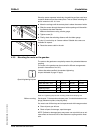
• If the lateral slots are used for mounting, the sensor cable cannot be
completely routed in the slots.
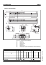
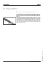
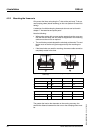
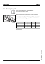
Figure 4.1 Fastening by means of clamping claws (1) and slot nuts from the
bottom (2)
The greater the load or the demands on the running accuracy, the
shorter the distance between the slot nuts or the clamping claws must
be.
C
A
B
1
2
Tapped hole distance PAS42 PAS43 PAS44
A [mm]7496130
B [mm] 88 112 150
C [mm]405070
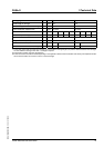
Maximum distance
1)
1) Recommended values per side at medium loads
PAS42 PAS43 PAS44
Clamping claws [mm] 600 800 1000
Slot nuts [mm] 600 800 1000