


MNA1MLSDM00EN, V2.01, 07.2009
PAS4•S 4 Installation
Portal axes with ball screw drive 55
4.3 Electrical installation
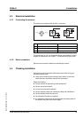
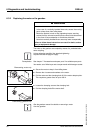
4.3.1 Connecting the sensors
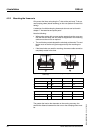
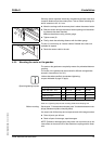
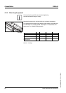
The sensors are equipped with an M8 x 1 connector.
Figure 4.2 Connection assignment sensors
The cable length is 100 mm. Extension cables are available in various
lengths as accessories, see chapter 7 "Accessories and spare parts".
4.3.2 Motor connection
See the motor manual for details on connecting the motor.
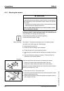
4.4 Checking installation
Verify that you have correctly installed the product after having per-
formed the above steps.
̈ Verify correct mounting and cabling of the product. In particular,
check the mains connection and the 24V connection.
Check the following:
̈ Did you connect all protective ground conductors?
̈ Do you use correct fueses?
̈ Are any live cable ends exposed?
̈ Did you properly install and connect all cables and connectors?
̈ Did you properly install the sensors?
̈ Do the sensors function as required?
̈ Is it possible to freely move the carriage with the contact plate for
the sensors along the entire travel length?
Pin Description Color
1 PELV supply voltage (+) BN (brown)
3 PELV supply voltage (-) BU (blue)
4 Output BK (black)
3
1
4
PNP
+
-
1 (+) 3 (-)
4
M8
3
1
4
NPN
+
-