


MNA1MLSDM00EN, V2.01, 07.2009
PAS4•S 4 Installation
Portal axes with ball screw drive 51
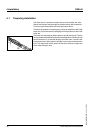
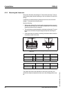
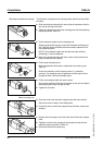
Since the sensor operates inductively, the switching surface must have
a specific distance from the contact plate. This so-called "switching dis-
tance" amounts to 0.5 ±0.1 mm.
̈ Move the carriage until the contact plate is above the sensor holder.
̈ Slide the sensor through the sensor holder opening until the switch-
ing distance has been reached.
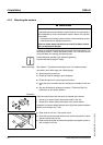
Measure the distance using a feeler gauge.
̈ Tighten screw (2).
̈ Finally, check the switching distance with the feeler gauge.
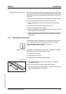
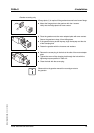
The slot (1) can hold up to 3 sensor cables. Suitable slot covers are
available on request.
̈ Route the sensor cable in the slot.
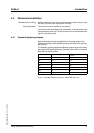
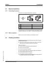
4.2.5 Mounting the motor or the gearbox
The motor or the gearbox are coupled by means of a preloaded elatomer
coupling.
The motor or the gearbox can be mounted in different arrangements
(turned in increments of 4 x 90°).
Unless otherwise specified, the standard tightening
torques indicated on page 47 apply.
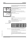
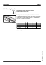
Special tightening torques
Table 4.2 Tightening torques and mounting dimensions clamping hub
Before mounting See chapter 7 "Accessories and spare parts" for suitable elastomer cou-
plings (elastomer spiders, clamping hubs).
You need a set of Allen keys and a torque wrench with hexagon socket.
̈ Clean all parts you will use.
̈ Check all parts for damage; repair damages.
NOTE: Polluted or damaged parts may cause run-out which has an ad-
verse effect on the service life of the elastomer coupling and the linear
axis.
2
1
Clamping hub PAS42 PAS43 PAS44
Screw ISO 4762 - 10.9 M6 x 16 M6 x 20 M8 x 25
Wrench size [mm] 5 5 6
Tightening torque [Nm] 14 14 35
Mounting dimension [mm] 13 14 14