


72 Portal axes with ball screw drive
7 Accessories and spare parts PAS4•S
MNA1MLSDM00EN, V2.01, 07.2009
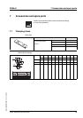
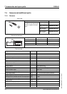
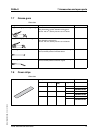
7.5 Sensors and additional parts
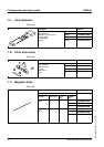
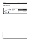
7.5.1 Sensors
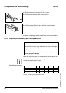
Order data
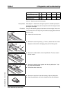
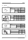
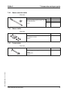
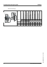
Dimensional drawings
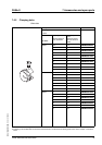
Technical data
Description Order no.
With signal state indicator, 100
mm cable and 3-pin M8 circular
connector, suitable for all axes
1 piece
PNP, normally
closed contact
XS508B1PBP01M8
PNP, normally open
contact
XS508B1PAP01M8
NPN, normally
closed contact
XS508B1NBP01M8
NPN, normally
open contact
XS508B1NAP01M8
1
4
3
Total length Thread length Cable length
A BL
[mm] [mm] [mm]
33 25 100
See chapter 4.3.1 "Connecting the sensors" for the connection assignment.
LED
A
B
M8
L
Design Cylindrical thread M8 x 1
Approvals CE
Electrical connection (PUR cable with M8 connector) [m] 0.10
Nominal switching distance S
n
(in the case of steel) [mm] 1.5
Hysteresis 1 to 15% of the real switching distance
Degree of protection as per IEC 60529 IP67
Temperature (storage) [°C] -40 ... +85
Temperature (operation) [°C] -25 ... +70
Housing material Nickel-plated brass
Cable material PUR, 3 x 0.12 mm
2
, length 10 cm
Function indicator output Yellow LED
Function indicator supply voltage No
Supply voltage (PELV) [V
dc
] 12 ... 24 with reverse polarity protection
Supply voltage (including residual ripple) [V
dc
] 10 ... 36
Switching current (overload and short-circuit protection) [mA] < 200
Voltage drop, output conducting [V] < 2
No-load current [mA] < 10
Maximum switching frequency [Hz] 5000
Switch-on time [ms] < 0.1
Switch-off time [ms] < 0.1