


MNA1MLSDM00EN, V2.01, 07.2009
PAS4•S 3 Technical Data
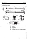
Portal axes with ball screw drive 29
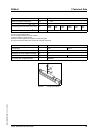
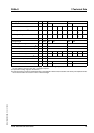
Carriage type Type 1 Type 4
Cover strip Yes No Yes No
Number of ball screw supports 0, 1 or
2
0120, 1 or
2
012
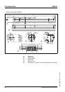
Total length of portal axis
1)
LP [mm] 466 +
X
369 +
X
399 +
X
429 +
X
646 +
X
549 +
X
579 +
X
609 +
X
Total length of support axis LS [mm] 382 +
X
285 +
X
315 +
X
345 +
X
562 +
X
465 +
X
495 +
X
525 +
X
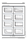
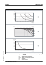
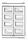
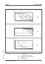
Stroke X [mm] See characteristics
Carriage length LC [mm] 323 226 503 406
Profile length of carriage F [mm] 190 370
Number of tapped holes for mounting
2)
n10 22
Distance between tapped holes [mm] 30 ±0.03 30 ±0.03
Limit switch position at drive end E0 [mm] 98 50 65 80 98 50 65 80
Limit switch position opposite drive end E1 [mm] 98 50 65 80 278 230 245 260
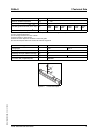
Stroke reserve to mechanical stop
3)
c [mm] 10 10
Length of cover strip clamp d [mm] 11.5 11.5
Deflection of cover strip D [mm] 48.5 - 48.5 -
Minimum distance between 2 carriages [mm] 90 35 90 35
1) In the case of axes with more than one carriage, you must add the carriage length (LC) and the distance between the carriages
for each additional carriage. More than 1 carriage on request.
2) Prepared for locating rings (see Accessories)
3) The stroke reserve must be increased depending on the application factors load, acceleration and velocity. The displacement dis-
tances must be taken into account in terms of the total length.