


50 Portal axes with ball screw drive
4 Installation PAS4•S
MNA1MLSDM00EN, V2.01, 07.2009
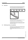
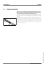
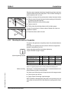
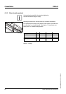
4.2.4 Mounting the sensors
A sensor is mounted to the axis body by means of a sensor holder. The
axis body provides a T slot for the sensor holder. This T slot has a cutout
at the end block for inserting the fastening nuts.
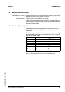
Unless otherwise specified, the standard tightening
torques indicated on page 47 apply.
Before mounting See chapter 7 "Accessories and spare parts" for suitable sensors.
You need a set of Allen keys and a feeler gauge.
̈ Clean all parts you will use.
̈ Check all parts for damage; repair damages.
̈ Check the sensor for correct type and function.
̈ Verify that your controller and your interface are suitable for the sen-
sor.
̈ See the dimensional drawings in chapter 3 "Technical Data" for
information on the sensor position..
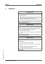
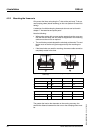
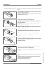
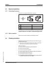
Procedure
2 M3 hex socket screw with hex nuts are located at the sensor.
• Screw (1) is used to fasten the sensor holder in the slot.
• Screw (2) is used to fasten the sensor in the sensor holder.
In addition, the sensor holder features cams (3) at both sides to keep the
sensor from turning in the T slot.
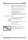
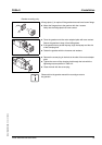
̈ Slide each nut into the T slot at the cutout.
̈ Place the the sensor holder with the two screws into position. Leave
the two screws loose at first.
̈ Slide the sensor holder to the desired position and tighten screw (1)
with a torque of 0.3 Nm.
@ WARNING
LOSS OF CONTROL
If unsuitable sensors are installed, ground faults or line interruptions
will be detected as an On state and will cause a failure of the protec-
tion function.
• If possible, use normally closed contacts as limit switches so that
a wire break can be signaled as an error.
Failure to follow these instructions can result in death, serious
injury or equipment damage.
1
2
3
1