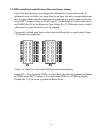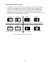
15
connector from the rear of the computer. Also note that the pin numbers are embossed on
the connector itself.
The +5V, +12V power lines are available on the connector. Precautionary measures
should be taken when using these supplies.
II
Warning
The maximum permissible current drawn on the I/O connector (P1) for the +5V
and +12V supplies are 250mA. Exceeding this can cause irreparable damage to
the PC 62C and your computer.
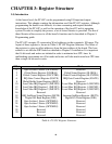
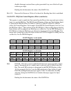
2.3) Description of Operation
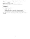
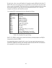
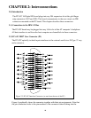
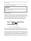
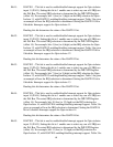
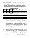
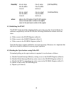
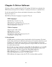
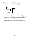
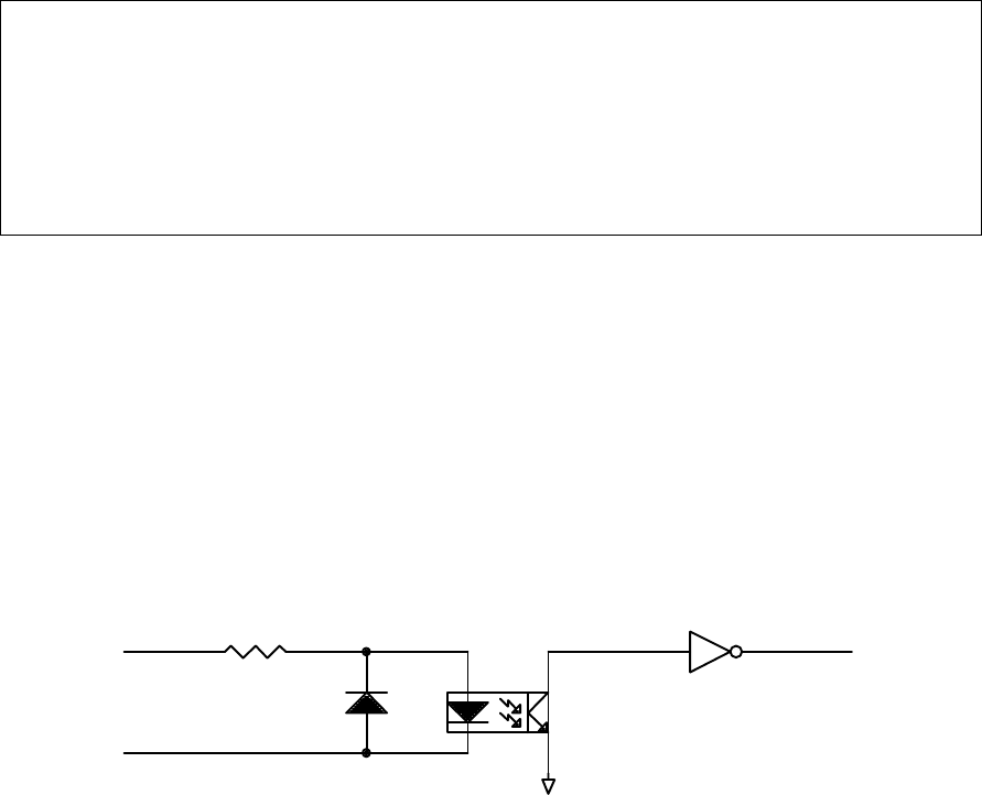
Looking into a single bit of input port, the external signal sees a diode. If the forward
voltage applied is greater than about 3.1V, the diode will conduct and the corresponding
bitin the port will reflect a 1 to the host computer. A logical high is defined from 3.1V to
a max of 24V. If the voltage applied between the input lines is less than 3.1V the
computer will interpret the input as a 0. A logical low pulse into the opto-isolator is
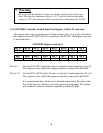
defined from 0 to 2.9V. Figure 2.3a illustrates the optically isolated connections.
From the above diagram, the minimum operating current for the input diode is about
6mA. Inputs are protected against reverse voltages up to 400V and are current limited. If
a reverse voltage is applied, the protection diode will clamp the reverse voltage to 0.7V.
The output is connected to the interrupt line of the IBM bus via associated circuitry and
is configured and controlled via software. Pulses above 3.1V to 24V will trigger the opto-
isolator in generating a TTL pulse to enable an IRQ. A voltage greater than 3.1V can also
trigger an interrupt in order to determine a status change in the inputs. This is useful in
multitasking enviroments such as Windows V3.11, Win ’95 and Win NT because the
PC62C will be accessed if an only if a status change in one of the port lines has occurred.
EXT
R3
IS1
GND
EXT-RET
Figure 2.3a: Optically Isolated Input Line