3
TABLE OF CONTENTS
Introduction...................................................................................................... 5
Typical applications...............................................................................................................................................................5
Key Features..........................................................................................................................................................................5
PC 62C Package ....................................................................................................................................................................6
The PC 62C package consists of: ...........................................................................................................................................6
Chapter 1: Installation .................................................................................... 7
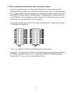
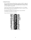
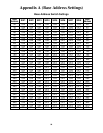
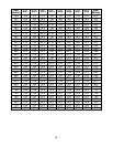
1.1) Setting the base address..................................................................................................................................................7
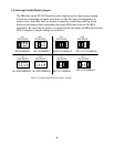
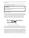
1.2) Wait State Generation on the PC 62C.............................................................................................................................9
1.3) Differential/Single-ended External Interrupt Jumper Setting.........................................................................................11
1.4) Interrupt Enable/Disable Jumpers.................................................................................................................................12
1.5) Connecting the PC 62C to the PC Backplane................................................................................................................13
CHAPTER 2: Interconnections .................................................................... 14
2.0) Introduction..................................................................................................................................................................14
2.1) Connections to the IBM AT Bus...................................................................................................................................14
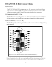
2.2) PC 62C DB37 User Connector (P1) ..............................................................................................................................14
2.3) Description of Operation...............................................................................................................................................15
2.4) Digital I/O Interface .....................................................................................................................................................17
2.5) Power supply connections.............................................................................................................................................18
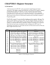
CHAPTER 3: Register Structure ................................................................. 19
3.0) Introduction..................................................................................................................................................................19
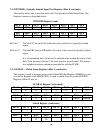
3.1) OPTORD0 - Optically Isolated Input Port Register (offset 0, read only)........................................................................20
3.2) GLOBAL – Global Status Register (offset 2, read/write)...............................................................................................20
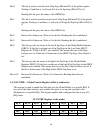
3.3) GLCNTRL – Global Control Register (offset 4, read/write)...........................................................................................21
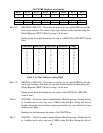
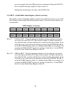
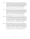
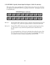
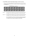
3.4) IGATE – IRQ Gate Control Register (offset 6, read/write)............................................................................................23
3.5) GBUF – Global Buffer Status Register (offset 8, read only)...........................................................................................28
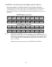
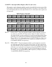
3.6) IMUXP0 – Local Mux Interrupt Control Register (offset 10, read/write).......................................................................29
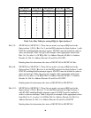
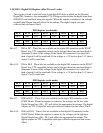
3.7) IMUXP1 – Local Mux Interrupt Control Register 2 (offset 12, read/write)....................................................................31
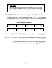
3.8) IMUXP2 – Local Mux Interrupt Control Register 3 (offset 14, read/write)....................................................................34
3.9) ISETX – Interrupt Set/Reset Register (offset 18, read / write) .......................................................................................36
3.10) DIO – Digital I/O Register (offset 20, read / write)......................................................................................................37
3.11) OPTORD1 - Optically Isolated Input Port Register 1 (offset 22, read only) .................................................................38
3.12) OPTORD2 - Optically Isolated Input Port Register 2 (offset 24, read only) .................................................................39
3.13) OPTORD3 - Optically Isolated Input Port Register 3 (offset 26, read only) .................................................................40
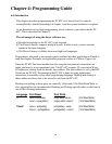
Chapter 4: Programming Guide................................................................... 41
4.0) Introduction..................................................................................................................................................................41
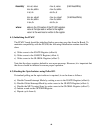
4.1) Initialising the PC62C..................................................................................................................................................42
4.2) Reading the Opto-Isolators using Polled I/O .................................................................................................................42
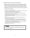
4.3) Configuring the Opto-Isolators using Shared Interrupt Mode........................................................................................43
4.4) Configuring the Opto-Isolators using Normal Interrupt Mode.......................................................................................44
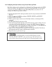
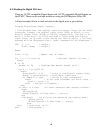
4.5) Reading the Digital I/O Lines.......................................................................................................................................45
Chapter 5: Driver Software .......................................................................... 46
5.1) Board Handles..............................................................................................................................................................46
5.2) Interrupt functions........................................................................................................................................................47
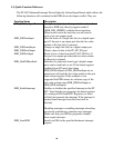
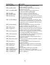
5.3) Quick Function Reference.............................................................................................................................................48
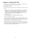
Chapter 6: Testing the PC 62C..................................................................... 50
6.1) Testing the PC 62C Board............................................................................................................................................50
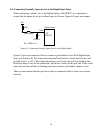
6.2) Connecting Normally Open devices to the Digital Input Lines......................................................................................51
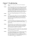
Chapter 7: Troubleshooting.......................................................................... 52
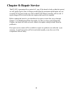
Chapter 8: Repair Service............................................................................. 54
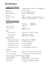
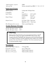
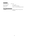
Specifications.................................................................................................. 55
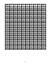
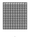
Appendix A (Base Address Settings) ............................................................ 58
Appendix B (PC62C Template)..................................................................... 66