36
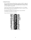
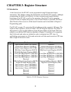
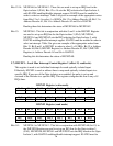
3.9) ISETX – Interrupt Set/Reset Register (offset 18, read / write)
This register is used to determine whether a positive level shift did occur in any one of the
Opto-Isolators when using Normal Interrupt share mode. The register is also used to reset
any of the flip-flops that was set by Opto-Isolator 0 to 16. 16 bit read to these registers are
recommended.
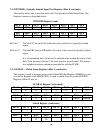
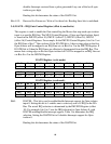
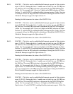
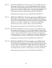
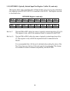
ISETX Register (read mode)
Bit 15 Bit 14 Bit 13 Bit 12 Bit 11 Bit 10 Bit 9 Bit 8
PBY7 PBY6 PBY5 PBY4 PBY3 PBY2 PBY1 PBY0
Bit 7 Bit 6 Bit 5 Bit 4 Bit 3 Bit 2 Bit 1 Bit 0
PAY7 PAY6
PAY5 PAY4 PAY3 PAY2 PAY1 PAY0
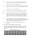
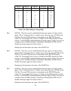
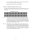
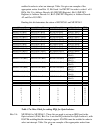
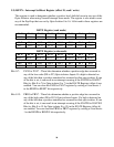
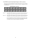
ISETX Register (write mode)
Bit 15 Bit 14 Bit 13 Bit 12 Bit 11 Bit 10 Bit 9 Bit 8
RESP15 RESP14 RESP13 RESP12 RESP11 RESP10 RESP9 RESP8
Bit 7 Bit 6 Bit 5 Bit 4 Bit 3 Bit 2 Bit 1 Bit 0
RESP7 RESP6 RESP5 RESP4 RESP3 RESP2 RESP1 RESP0
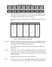
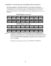
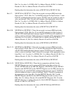
Bits 0-7: PAY0 to PAY7 - These bits determine whether a positive edge has occurred in
any of the low order (D0 to D7) Opto-isolators Inputs. If a high is detected on
any of the bits then a positive transition has occurred on that opto-isolator. If one
of the bits is set, it can result in an interrupt occuring if the IGATE0 to IGATE7
Bits (ie: Bits 0 to 7 for Opto-isolator 0 to 7) in the IGATE Register (offset 6) are
enabled. You can clear the PAX0 to PAX7 registers by writing a 0 and then a 1
to the RESP0 to RESP7 bit respectively.
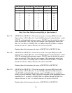
Bits 8-15: PBX0 to PBX7 - These bits determine whether a positive edge has occurred in
any of the high order (D8 to D15) Opto-isolators Inputs. If a high is detected on
any of the bits then a positive transition has occurred on that opto-isolator. If one
of the bits is set, it can result in an interrupt occuring if the IGATE8 to IGATE15
Bits (ie: Bits 8 to 15 for Opto-isolator 8 to 15) in the IGATE Register (offset 6)
are enabled. You can clear the PBX0 to PBX7 registers by writing a 0 and then a
1 to the RESP8 to RESP15 bit respectively.