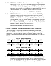
24
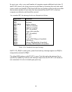
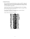
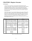
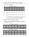
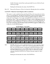
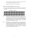
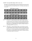
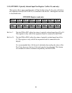
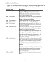
IMUX2
IMUX1 IMUX0 IGATE0 IRQ
Bit 2
Bit 1 Bit 0 IGATE0 IRQ
0 0 0 1 10
0 0 1 1 11
0 1 0 1 12
0 1 1 1 15
1 0 0 1 2
1 0 1 1 7
1 1 0 1 5
1 1 1 1 3
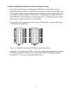
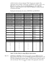
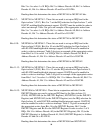
Table 3.4a: Mux Table for setting IRQs
Bit1: IGATE1 – This bit is used to enable/disable Interrupt support for Opto-isolator
input 1 (PA1). Setting this bit to 1 enables one to select any one of 8 IRQ on the
ISA Bus. The actual IRQ selection is determined by the IMUXP0 Register
(offset 10). For example, bits 3 (low) to 5 (high) sets the IRQ selection on Opto-
Isolator 1, with IGATE0 enabling/disabling interrupt support. Table 3.4a gives an
example of how the IRQ selection is determined. Setting the IGATE1 bit to 0
disables Interrupts support for Opto-isolator 1.
Reading this bit determines the status of the IGATE1 bit.
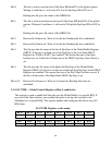
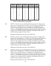
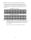
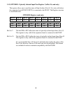
Bit2: IGATE2 – This bit is used to enable/disable Interrupt support for Opto-isolator
input 2 (PA2). Setting this bit to 1 enables one to select any one of 8 IRQs on the
ISA Bus. The actual IRQ selection is determined by the IMUXP0 Register
(offset 10). For example, bits 6 (low) to 8 (high) set the IRQ selection for Opto-
Isolator 2, with IGATE0 enabling/disabling interrupt support. Table 3.4a gives an
example of how the IRQ selection is determined. Setting the IGATE2 bit to 0
disables Interrupts support for Opto-isolator 2.
Reading this bit determines the status of the IGATE2 bit.
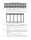
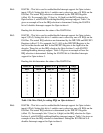
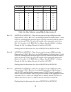
Bit3: IGATE3 – This bit is used to enable/disable Interrupt support for Opto-isolator
input 3 (PA3). Setting this bit to 1 enables one to select any one of 8 IRQs on the
ISA Bus. The actual IRQ selection is determined by the IMUXP0 Register
(offset 10). For example, bits 9 (low) to 11 (high) set the IRQ selection for Opto-
Isolator 3, with IGATE3 enabling/disabling interrupt support. Table 3.4a gives an
example of how the IRQ selection is determined. Setting the IGATE3 bit to 0
disables Interrupts support for Opto-isolator 3.
Reading this bit determines the status of the IGATE3 bit.