32
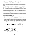
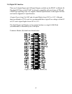
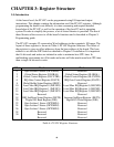
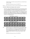
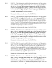
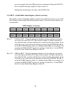
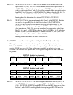
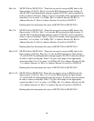
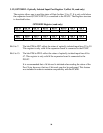
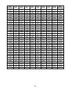
enabled in order to select an interrupt. Table 3.6a gives an example of the
appropriate writes from Bits 15, Bit 0 and 1 in IMUXP1 in order to select 1 of 8
IRQs. Bit 15 is Address Decode A0 (IMUXP0 Register), Bit 0 (IMUXP1
Register) is Address Decode A1, Bit 2 (IMUXP1 Register) is Address Decode
A2 and Gx is IGATE5.
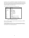
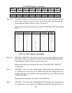
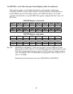
Reading this bit determines the status of MUXP5A1 and MUXP5A2.
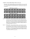
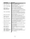
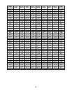
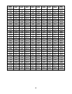
Address A2 Address A1 Address A0 Gate Cntrl IRQ
MUXP0A2 (Bit2) MUXP0A1 (Bit1) MUXP0A0 (Bit0) IGATE0 (Bit0)
MUXP1A2 (Bit5) MUXP1A1 (Bit4) MUXP1A0 (Bit3) IGATE1 (Bit1)
MUXP2A2 (Bit8) MUXP2A1 (Bit7) MUXP2A0 (Bit6) IGATE2 (Bit2)
MUXP3A2 (Bit11) MUXP3A1 (Bit10) MUXP3A0 (Bit9) IGATE3 (Bit3)
MUXP4A2 (Bit14) MUXP4A1 (Bit13) MUXP4A0 (Bit12) IGATE4 (Bit4)
MUXP5A2 (Bit1) MUXP5A1 (Bit0) MUXP5A0 (Bit15) IGATE5 (Bit5)
MUXP6A2 (Bit4) MUXP6A1 (Bit3) MUXP6A0 (Bit2) IGATE6 (Bit6)
MUXP7A2 (Bit7) MUXP7A1 (Bit6) MUXP7A0 (Bit5) IGATE7 (Bit7)
MUXP8A2 (Bit10) MUXP8A1 (Bit9) MUXP8A0 (Bit8) IGATE8 (Bit8)
MUXP9A2 (Bit13) MUXP9A1 (Bit12) MUXP9A0 (Bit11) IGATE9 (Bit9)
MUXP10A2 (Bit0) MUXP10A1 (Bit15) MUXP10A0 (Bit14) IGATE10
(Bit10)
MUXP11A2 (Bit3) MUXP11A1 (Bit2) MUXP11A0 (Bit1) IGATE11
(Bit11)
MUXP12A2 (Bit6) MUXP12A1 (Bit5) MUXP12A0 (Bit4) IGATE12
(Bit12)
MUXP13A2 (Bit9) MUXP13A1 (Bit8) MUXP13A0 (Bit7) IGATE13
(Bit13)
MUXP14A2 (Bit12) MUXP14A1 (Bit11) MUXP14A0 (Bit10) IGATE14
(Bit14)
MUXP15A2 (Bit15) MUXP15A1 (Bit14) MUXP15A0 (Bit13) IGATE15
(Bit15)
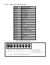
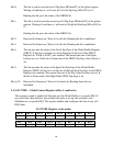
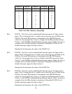
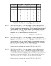
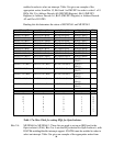
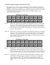
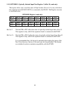
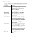
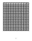
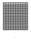
A2 A1 A0 IGATE IRQ
0 0 0 1 10
0 0 1 1 11
0 1 0 1 12
0 1 1 1 15
1 0 0 1 2
1 0 1 1 7
1 1 0 1 5
1 1 1 1 3
Table 3.7a: Mux Table for setting IRQs for Opto-Isolators
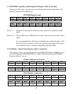
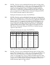
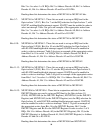
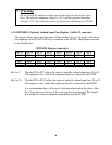
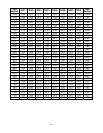
Bits 2-4: MUXP6A0 to MUXP6A2 - These bits are used to set up an IRQ line for the
Opto-isolator 6 (PA6). Bits 2 to 4 sets the IRQ selection for Opto-Isolator 6, with
IGATE6 enabling/disable interrupt support. IGATE6 must be enabled in order to
select an interrupt. Table 3.6a gives an example of the appropriate writes from