31
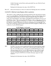
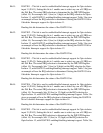
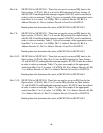
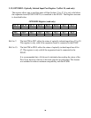
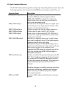
Bits 12-14: MUXP4A0 to MUXP4A2 - These bits are used to set up an IRQ line for the
Opto-isolator 4 (PA4). Bits 12 to 14 sets the IRQ selection for Opto-Isolator 4,
with IGATE4 enabling/disable interrupt support. IGATE4 must be enabled in
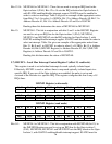
order to select an interrupt. Table 3.6a gives an example of the appropriate writes
from Bits 12 to 14 to select 1 of 8 IRQs. Bit 12 is Address Decode A0, Bit 13 is
Address Decode A1, Bit 14 is Address Decode A2 and Gx is IGATE4.
Reading these bits determines the status of MUXP4A0 to MUXP4A2.
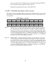
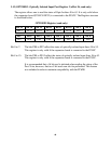
Bits 15: MUXP5A0 - This bit in conjunction with bits 0 and 1 in the IMUXP1 Register
are used to set up an IRQ line for the Opto-isolator 5 (PA5). MUXP5A0,
MUXP5A1 and MUXP5A2 sets the IRQ selection for Opto-Isolator 5, with
IGATE5 enabling/disable interrupt support. IGATE5 must be enabled in order to
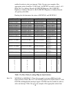
select an interrupt. Table 3.6a gives an example of the appropriate writes from
Bits 15, Bit 0 and 1 in IMUXP1 in order to select 1 of 8 IRQs. Bit 15 is Address
Decode A0, Bit 0 (IMUXP1 Register) is Address Decode A1, Bit 2 (IMUXP1
Register) is Address Decode A2 and Gx is IGATE5.
Reading this bit determines the status of MUXP5A0.
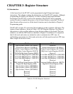
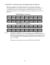
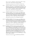
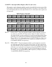
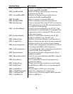
3.7) IMUXP1 – Local Mux Interrupt Control Register 2 (offset 12, read/write)
This register is used to set individual interrupts for each optically isolated input.
Effectively MUXP1 is used as address lines to map each optically isolated inputs to a
specific IRQ. If any one of the Opto-isolators was enabled, the pulse is set up and
vectored to the Decoder to a specific IRQ. This register configures this line to any of 8
IRQs lines.
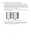
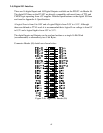
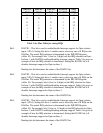
IMUXP1 Register (write mode)
Bit 15 Bit 14 Bit 13 Bit 12 Bit 11 Bit 10 Bit 9 Bit 8
MUXP10A1 MUXP10A0 MUXP9A2 MUXP9A1 MUXP9A0 MUXP8A2 MUXP8A1 MUXP8A0
Bit 7 Bit 6 Bit 5 Bit 4 Bit 3 Bit 2 Bit 1 Bit 0
MUXP7A2 MUXP7A1
MUXP7A0 MUXP6A2
MUXP6A1 MUXP6A0 MUXP5A2
MUXP5A1
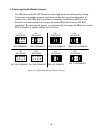
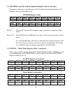
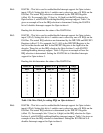
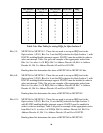
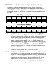
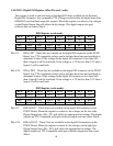
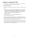
IMUXP1 Register (read mode)
Bit 15 Bit 14 Bit 13 Bit 12 Bit 11 Bit 10 Bit 9 Bit 8
MUXP10A1
MUXP10A0
MUXP9A2
MUXP9A1
MUXP9A0
MUXP8A2
MUXP8A1
MUXP8A0
Bit 7 Bit 6 Bit 5 Bit 4 Bit 3 Bit 2 Bit 1 Bit 0
MUXP7A2 MUXP7A1
MUXP7A0 MUXP6A2
MUXP6A1 MUXP6A0 MUXP5A2
MUXP5A1
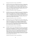
Bits 0-1: MUXP5A1 to MUXP5A2 - This bit in conjunction with MUXP5A0 (bit 15) in
the IMUXP0 Register are used to set up an IRQ line for the Opto-isolator 5
(PA5). MUXP5A0, MUXP5A1 and MUXP5A2 sets the IRQ selection for Opto-
Isolator 5, with IGATE5 enabling/disable interrupt support. IGATE5 must be