20
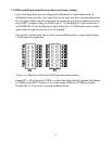
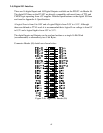
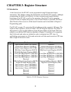
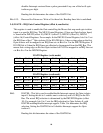
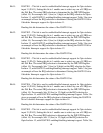
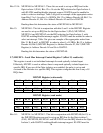
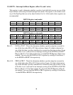
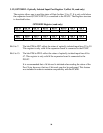
3.1) OPTORD0 - Optically Isolated Input Port Register (offset 0, read only)
The register allows one to read the status of all 16 Optically Isolated Input Lines. The
Register structure is described below.
OPTORD0 Register (read)
Bit 15 Bit 14 Bit 13 Bit 12 Bit 11 Bit 10 Bit 9 Bit 8
PB7 PB6 PB5 PB4 PB3 PB2 PB1 PB0
Bit 7 Bit 6 Bit 5 Bit 4 Bit 3 Bit 2 Bit 1 Bit 0
PA7 PA6 PA5 PA4 PA3 PA2 PA1 PA0
Bit 0 to 7: The bits PA7 down to PA0 reflect the status of the first 8 optically isolated
inputs.
Bit 8 to 15: The bits PB7 down to PB0 reflect the status of the second 8 optically isolated
inputs.
It is recommended that a 16 bit read is initiated when reading the status of the
Port. Note, however, that two 8 bit reads can also be performed. This feature
was included in order to maintain compatibility with the PC62B.
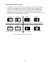
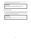
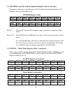
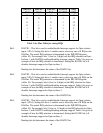
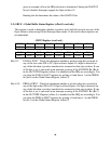
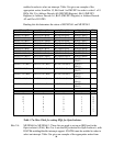
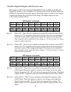
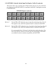
3.2) GLOBAL – Global Status Register (offset 2, read/write)
This register is used to monitor and reset the Global IRQ Set Register. GRES0/1 is used
to reset the Register while GIRQTOG0/1 is used to check if any bit in the OPTORD
Register (Offset 0) was set.
GLOBAL Register (write mode)
Bit 15 Bit 14 Bit 13 Bit 12 Bit 11 Bit 10 Bit 9 Bit 8
0 0 0 0 0 0 0 0
Bit 7 Bit 6 Bit 5 Bit 4 Bit 3 Bit 2 Bit 1 Bit 0
0 0 0 0 0 0 GRES1 GRES0
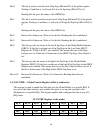
Global Register (read mode)
Bit 15 Bit 14 Bit 13 Bit 12 Bit 11 Bit 10 Bit 9 Bit 8
x x x x x x x x
Bit 7 Bit 6 Bit 5 Bit 4 Bit 3 Bit 2 Bit 1 Bit 0
x x GIRQTO
G1
GIRQTO
G0
GIRQEN1
GIRQEN0
GRES1 GRES0