27
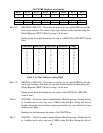
Bit11: IGATE11 – This bit is used to enable/disable Interrupt support for Opto-isolator
input 11 (PA11). Setting this bit to 1 enables one to select any one of 8 IRQs on
the ISA Bus. The actual IRQ selection is determined by the IMUXP2 Register
(offset 14). For example, bits 1 (low) to 3 (high) set the IRQ selection for Opto-
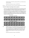
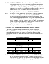
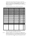
Isolator 11, with IGATE11 enabling/disabling interrupt support. Table 3.4a gives
an example of how the IRQ selection is determined. Setting the IGATE11 bit to
0 disables Interrupts support for Opto-isolator 11.
Reading this bit determines the status of the IGATE11 bit.
Bit12: IGATE12 – This bit is used to enable/disable Interrupt support for Opto-isolator
input 12 (PA12). Setting this bit to 1 enables one to select any one of 8 IRQs on
the ISA Bus. The actual IRQ selection is determined by the IMUXP2 Register
(offset 14). For example, bits 4 (low) to 6 (high) set the IRQ selection for Opto-
Isolator 12, with IGATE12 enabling/disabling interrupt support. Table 3.4a gives
an example of how the IRQ selection is determined. Setting the IGATE12 bit to
0 disables Interrupts support for Opto-isolator 12.
Reading this bit determines the status of the IGATE12 bit.
Bit13: IGATE13 – This bit is used to enable/disable Interrupt support for Opto-isolator
input 13 (PA13). Setting this bit to 1 enables one to select any one of 8 IRQs on
the ISA Bus. The actual IRQ selection is determined by the IMUXP2 Register
(offset 14). For example, bits 7 (low) to 9 (high) set the IRQ selection for Opto-
Isolator 13, with IGATE13 enabling/disabling interrupt support. Table 3.4a gives
an example of how the IRQ selection is determined. Setting the IGATE13 bit to
0 disables Interrupts support for Opto-isolator 13.
Reading this bit determines the status of the IGATE13 bit.
Bit14: IGATE14 – This bit is used to enable/disable Interrupt support for Opto-isolator
input 14 (PA14). Setting this bit to 1 enables one to select any one of 8 IRQs on
the ISA Bus. The actual IRQ selection is determined by the IMUXP2 Register
(offset 14). For example, bits 10 (low) to 12 (high) set the IRQ selection for
Opto-Isolator 14, with IGATE14 enabling/disabling interrupt support. Table 3.4a
gives an example of how the IRQ selection is determined. Setting the IGATE14
bit to 0 disables Interrupts support for Opto-isolator 14.
Reading this bit determines the status of the IGATE14 bit.
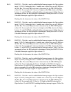
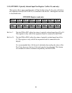
Bit15: IGATE15 – This bit is used to enable/disable Interrupt support for Opto-isolator
input 15 (PA15). Setting this bit to 1 enables one to select any one of 8 IRQs on
the ISA Bus. The actual IRQ selection is determined by the IMUXP2 Register
(offset 14). For example, bits 13 (low) to 15 (high) set the IRQ selection for
Opto-Isolator 15, with IGATE15 enabling/disabling interrupt support. Table 3.4a