43
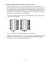
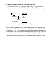
4.3) Configuring the Opto-Isolators using Shared Interrupt Mode
Each Opto-isolator can be configured to used an Interrupt Line. However, since only 8
IRQ Lines are available, interrupt sharing should be used. The Global Status Register
should be initialised in order to map a positive level shift to an IRQ Line. The 16 Opto-
Isolators are divided into the low order 8 and a high order 8. The first 8 lines will then
be mapped to a single shared IRQ line while the last eight lines mapped to another single
shared IRQ Line. The reason for the division is to prioritise the first 8 lines and the last 8
lines. The Procedure is as follows:
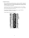
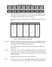
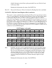
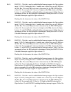
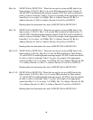
a) Write C0h to the GLCNTRL Register.
b) Write F4h to the GLCNTRL Register (Set sets up IRQ2 for the first 8 Opto-Isolators
and IRQ5 for the high order (D8 to D15) Opto Isolators.
c) Setup an ISR for IRQx and IRQy (in this example it is 2 and 5)
d) When a positive edge is seen on one of the Opto-isolators, an interrupt will be
generated (either in the first eight or the last 8).
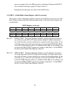
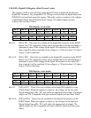
e) An ISR should check which opto-isolator has changed state by reading the GBUF
Register (using one single 16 bit read).
f) After determining which opto-isolator has changed state, proceed with the necessary
action.
g) If any other opto-isolator has changed state (after reading the GBUF register)
proceed with the necessary action.
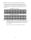
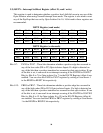
h) Clear the Interrupt Enable flip-flops after all the necessary action is taken. You can
clear either each individual flip-flips by writing to the ISETX Register (Offset or
reset the first eight or last 8 flip-flops by writing a 0 and then a 1 to the GRES0 (bit
0) or GRES1 (bit1) in the GLOBAL Register (Offset 2).
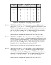
i) Issue an End of Interrupt (EOI) command to the Interrupt controller. Note that an
EOI command must be issued to both Interrupt Controllers.
j) Repeat the above cycle from e) to i).
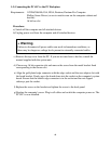
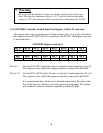
II Warning
Do not configure both IRQ MUXes in the GLCNTRL Register to the same
Interrupt. This will lead to two open collector lines driving each other and
can yield inexplicable results.