50
Chapter 6: Testing the PC 62C
Before attempting to interface the PC 62C with your application, it is essential that you
test the board first. This is done using the following procedure:
6.1) Testing the PC 62C Board
Install the PC 62C using the procedure described in the Chapter 2: Installation. Proceed as
follows:
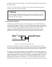
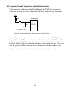
a) Make a test loom by connecting the digital outputs [DO0-DO15] to the Digital Inputs
[DI0-DI15]. Also connect the Digital Outputs [DO0-D15] to the optically isolated
inputs [PA0-7] to [DO0-DO7] and [PB0-7] to [DO8-DO15] respectively. All the
return lines should be connected to GND on the digital I/O connector. COMA and
COMB should be connected to GND on the DB37 Connector.
b) Switch the Computer on
c) On the DOS prompt, go to the C:\EDR\TPAS\DEMOS\ sub-directory
d) Run the 62CTEST.EXE Test program.
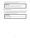
If an error message 'Board not found' appear on your screen then the PC 62C was not
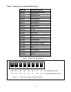
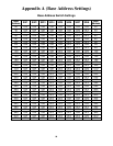
installed at that address. Try a different base address as specified in Apendix A (eg: 700h)
and re-run the test S/W. If the problem persists then try increasing the wait states on the
PC 62C Board and re-run test software. The board should work.
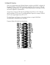
If the PC 62C is found, a message will appear on the screen: 'PC 62C Board found'. The
program comprehensively tests the register structure and each optically isolated input line.
You may feed any voltage on the optically isolated input lines up to a maximum of 24V.
Any TTL signals can be fed into the digital I/O lines.