28
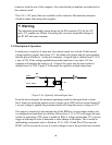
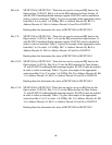
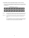
gives an example of how the IRQ selection is determined. Setting the IGATE15
bit to 0 disables Interrupts support for Opto-isolator 15.
Reading this bit determines the status of the IGATE15 bit.
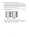
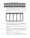
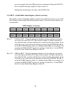
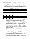
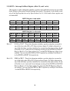
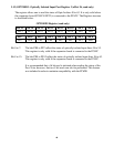
3.5) GBUF – Global Buffer Status Register (offset 8, read only)
This register is used to determine whether a positive level shift did occur in any one of the
Opto-Isolators when using Global Interrupt share mode. 16 bit read to these registers are
recommended.
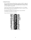
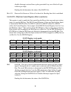
GBUF Register (read only)
Bit 15 Bit 14 Bit 13 Bit 12 Bit 11 Bit 10 Bit 9 Bit 8
PBX7 PBX6 PBX5 PBX4 PBX3 PBX2 PBX1 PBX0
Bit 7 Bit 6 Bit 5 Bit 4 Bit 3 Bit 2 Bit 1 Bit 0
PAX7 PAX6
PAX5 PAX4 PAX3 PAX2 PAX1 PAX0
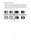
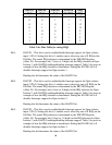
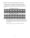
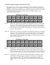
Bits 0-7: PAX0 to PAX7 - These bits determine whether a positive edge has occurred in
any of the low order (D0 to D7) Opto-isolators Inputs. If a high is detected on
any of the bits then a positive transition has occurred on that opto-isolator. If one
of the bits is set, it can result in an interrupt occuring if the IGATEG0 Bit (Bit 6)
in the GLCNTRL Register (offset 4) is enabled and the IRQ set accordingly. You
can clear the PAX0 to PAX7 registers by writing a 0 and then a 1 to the GRES0
bit (bit 0) in the Global Status Register (offset 2).
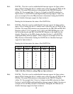
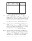
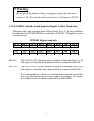
Bits 8-15: PBX0 to PBX7 - These bits determine whether a positive edge has occurred in
any of the high order (D8 to D15) Opto-isolators Inputs. If a high is detected on
any of the bits then a positive transition has occurred on that opto-isolator. If one
of the bits is set, it can result in an interrupt occuring if the IGATEG1 Bit (Bit 7)
in the GLCNTRL Register (offset 4) is enabled and the IRQ set accordingly. You
can clear the PBX0 to PBX7 registers by writing a 0 and then a 1 to the GRES1
bit (bit 1) in the Global Status Register (offset 2).