30
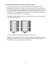
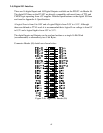
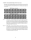
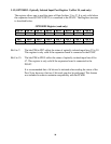
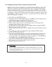
MUXP0A2
MUXP0A1 MUXP0A0 IGATE0 IRQ
Bit 2
Bit 1 Bit 0
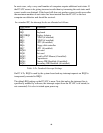
A2 A1 A0 Gx
0 0 0 1 10
0 0 1 1 11
0 1 0 1 12
0 1 1 1 15
1 0 0 1 2
1 0 1 1 7
1 1 0 1 5
1 1 1 1 3
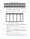
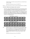
Table 3.6a: Mux Table for setting IRQs for Opto-Isolator 0
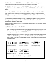
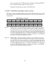
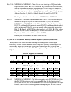
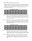
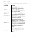
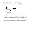
Bits 3-5: MUXP1A0 to MUXP1A2 - These bits are used to set up an IRQ line for the
Opto-isolator 1 (PA1). Bits 3 to 5 sets the IRQ selection for Opto-Isolator 1, with
IGATE1 enabling/disable interrupt support. IGATE1 must be enabled in order to
select an interrupt. Table 3.6a gives an example of the appropriate writes from
Bits 3 to 5 to select 1 of 8 IRQs. Bit 3 is Address Decode A0, Bit 4 is Address
Decode A1, Bit 5 is Address Decode A2 and Gx is IGATE1.
Reading these bits determines the status of MUXP1A0 to MUXP1A2 bits.
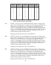
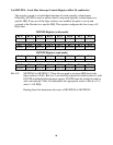
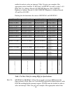
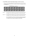
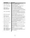
Bits 6-8: MUXP2A0 to MUXP2A2 - These bits are used to set up an IRQ line for the
Opto-isolator 2 (PA2). Bits 6 to 8 sets the IRQ selection for Opto-Isolator 2, with
IGATE2 enabling/disable interrupt support. IGATE2 must be enabled in order to
select an interrupt. Table 3.6a gives an example of the appropriate writes from
Bits 6 to 8 to select 1 of 8 IRQs. Bit 6 is Address Decode A0, Bit 7 is Address
Decode A1, Bit 8 is Address Decode A2 and Gx is IGATE2.
Reading these bits determines the status of MUXP2A0 to MUXP2A2.
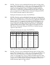
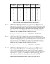
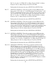
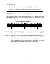
Bits 9-11: MUXP3A0 to MUXP3A2 - These bits are used to set up an IRQ line for the
Opto-isolator 3 (PA3). Bits 9 to 11 sets the IRQ selection for Opto-Isolator 3,
with IGATE3 enabling/disable interrupt support. IGATE3 must be enabled in
order to select an interrupt. Table 3.6a gives an example of the appropriate writes
from Bits 9 to 11 to select 1 of 8 IRQs. Bit 9 is Address Decode A0, Bit 10 is
Address Decode A1, Bit 11 is Address Decode A2 and Gx is IGATE3.
Reading these bits determines the status of MUXP3A0 to MUXP3A2.